
Remote monitoring method for gas pipeline

A gas pipeline and remote monitoring technology, which is applied in the direction of program control, computer control, general control system, etc., can solve the problems of inconvenient long-term use and low efficiency of gas monitoring, and achieve the effect of easy monitoring and accident prevention

Inactive Publication Date: 2018-12-28
四川川油工程技术勘察设计有限公司
View PDF0 Cites 0 Cited by
  • Summary
  • Abstract
  • Description
  • Claims
  • Application Information

AI Technical Summary

Problems solved by technology

[0003] The technical problem to be solved by the present invention is that the existing gas monitoring efficiency is low, and it is not convenient for long-term use. The purpose is to provide a remote monitoring method for gas pipelines to solve the problem of gas monitoring

Method used


Image

  • Remote monitoring method for gas pipeline

Examples


Embodiment 1

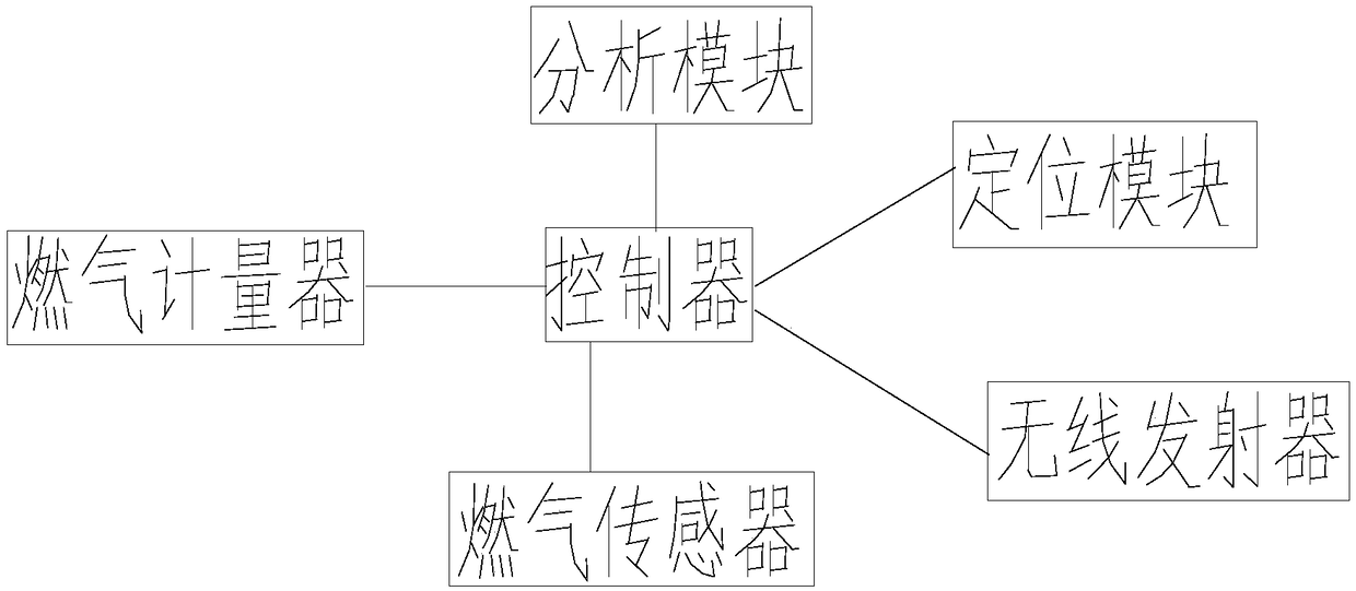
[0019] Such as figure 1 As shown, a gas pipeline remote monitoring method of the present invention comprises the following steps:

[0020] (1) The positioning module and the gas sensor detect the gas of each household. The gas sensor is used to detect whether there is gas outside the pipeline. When there is gas leakage, the signal is sent to the terminal through the wireless transmitter connected to the controller;

[0021] (2) The gas meter detects the throughput of gas in each household, and sends the detected information to the terminal;

[0022] (3) The gas sensor sends the concentration of the external gas to the terminal through the wireless transmitter.

[0023] In step (3), the gas sensor sends the concentration of the external gas to the controller, and the controller sends the information to the analysis module, which analyzes and compares the obtained information, and if the information is abnormal, sends the information to the terminal.

[0024] The gas sensor a...


PUM


Abstract

The invention discloses a remote monitoring method for a gas pipeline. A positioning module and a gas sensor are used for detecting the gas of each household; the gas sensor is used for detecting whether gas exists outside the pipeline or not; when gas leakage occurs, a signal is sent to a terminal through a wireless transmitter connected with the controller; a gas meter is used for detecting thegas flow through each household, and sending the detected information to the terminal; and the gas sensor is used for transmitting the concentration of external gas to the terminal through the wireless transmitter. The system can directly send the abnormal location to the terminal, which is more convenient and effective for monitoring, and accidents are prevented.

Description

technical field [0001] The invention relates to the field of gas monitoring, in particular to a method for remote monitoring of gas pipelines. Background technique [0002] With the development of society, gas fuels such as natural gas and liquefied petroleum gas have gradually replaced traditional solid fuels such as wood and coal. Mass welcome. However, although gas has many advantages, it also has relatively high risks. While gas provides convenience to millions of households, it also causes many accidents. Therefore, real-time dynamic monitoring of gas is particularly important. However, traditional monitoring and alarm devices can only alarm indoors, and cannot transmit alarm signals to other relevant places. Once there is no one at home, the monitoring and alarm devices will lose their effect. Contents of the invention [0003] The technical problem to be solved by the present invention is that the existing gas monitoring efficiency is low, and it is not convenien...

Claims


Application Information

Patent Timeline
IPC IPC(8): G05B19/048
CPCG05B19/048
Inventor 曾道贵黄玲
Owner 四川川油工程技术勘察设计有限公司
Learn More