
Cleaning and drying equipment for valve production

A drying equipment and cleaning technology, applied in the direction of cleaning method using liquid, drying gas arrangement, lighting and heating equipment, etc., can solve the problems of easy adhesion of dust, cleaning and drying can not be carried out in one equipment, etc. Easy to fix, easy to clean and dry work, improve efficiency

Inactive Publication Date: 2018-12-28
ANHUI WODE VALVE MFG
View PDF11 Cites 0 Cited by
  • Summary
  • Abstract
  • Description
  • Claims
  • Application Information

AI Technical Summary

Problems solved by technology

In order to ensure the working quality of the hollow valve, it is necessary to ensure that the valve is clean and dry before flushing the valve with sodium, so as to ensure that the follow-up work can be carried out normally. When cleaning the valve, the valve is usually cleaned first, and then taken out for drying For the work, cleaning and drying cannot be carried out in one equipment. After cleaning, the process before drying is easy to stick to dust

Method used


Image

  • Cleaning and drying equipment for valve production
  • Cleaning and drying equipment for valve production
  • Cleaning and drying equipment for valve production

Examples


Embodiment Construction

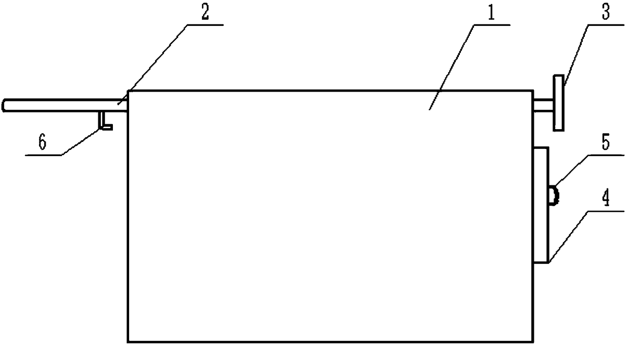
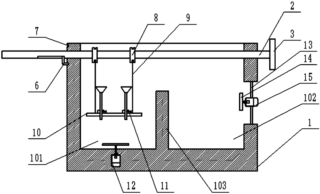
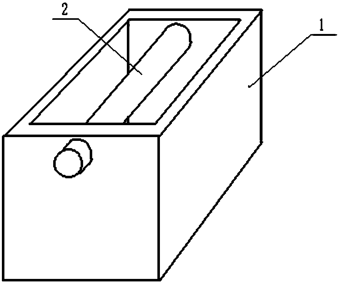
[0020] Such as Figure 1 to Figure 3 As shown, it is a cleaning and drying equipment for valve production proposed by the present invention, which is characterized in that it includes a housing 1, a cleaning cabin 101, an air-drying cabin 102, a partition 103, a movable rod 2, a turntable 3, and two steel cables 9. Hanging plate 10, first motor 12 and second motor 15;

[0021] The movable rod 2 passes through the upper end of the housing 1 and is slidably connected with the housing 1. The sliding direction of the movable rod 2 is horizontal; the turntable 3 is fixedly installed at the end of the movable rod 2; Slot 8; the first ends of the steel cables 9 are all connected to the winding groove 8, and the ends of the two steel cables 9 are fixedly connected to the two ends of the hanging plate 10.

[0022] Clean cabin 101 and air-dry cabin 102 are all arranged on housing 1 inside, and dividing plate 103 is arranged between clean cabin 101 and air-dry cabin 102; 102 moves, com...


PUM


Abstract

The invention discloses cleaning and drying equipment for valve production. The cleaning and drying equipment comprises a shell, a cleaning cabin, an air drying cabin, a separation plate, a movable rod, a rotary table, two steel cables, a hanging plate, a first motor and a second motor. The movable rod penetrates through the upper end of the shell and is slidably connected with the shell, the sliding direction of the movable rod is the horizontal direction; the rotary table is fixedly mounted at the tail end of the movable rod; two winding grooves corresponding to the steel cables are formed in the movable rod; the first ends of the steel cables are connected to the winding grooves, and the tail ends of the two steel cables are fixedly connected to the two ends of the hanging plate; the cleaning cabin and the air drying cabin are disposed inside the shell, and the separation plate is disposed between the cleaning cabin and the air drying cabin; the first motor is disposed at the bottomof the cleaning cabin; and the second motor is mounted at the side end of the air drying cabin through a connecting rod. The cleaning and drying equipment can internally integrate the cleaning and air drying work of a valve, improves the working efficiency, and can prevent the valve from being polluted by the outside before being air-dried.

Description

technical field [0001] The invention relates to the technical field of valve production, in particular to a cleaning and drying equipment for valve production. Background technique [0002] The valve is an important part of the engine. The function of the valve is to input air into the engine and remove the exhaust gas after combustion. From the structure of the engine, the valves have intake valves and exhaust valves. Classified from the finished structure of the valve, it is usually divided into a whole valve, a bimetallic butt welding valve and a hollow sodium-filled valve. In order to ensure the working quality of the hollow valve, it is necessary to ensure that the valve is clean and dry before flushing the valve with sodium, so as to ensure that the follow-up work can be carried out normally. When cleaning the valve, the valve is usually cleaned first, and then taken out for drying The work, cleaning and drying cannot be carried out in one piece of equipment. After c...

Claims


Application Information

Patent Timeline
IPC IPC(8): B08B3/08B08B3/10B08B13/00F26B21/00
CPCB08B3/08B08B3/102B08B13/00F26B21/001
Inventor 林青锋
Owner ANHUI WODE VALVE MFG
Learn More