Vacuum assist toilet trap

A flush toilet and vacuum-assisted technology, applied in water supply devices, flush toilets, flushing equipment with water tanks, etc., can solve problems such as not being too small

Inactive Publication Date: 2002-09-11
FLUIDMASTER
View PDF1 Cites 0 Cited by
  • Summary
  • Abstract
  • Description
  • Claims
  • Application Information

AI Technical Summary

Problems solved by technology

A good flushing effect can be obtained when the gap over the sink is small, but a gap not too small in height, for example one centimeter, must be used to ensure that air can pass through the top of the lower bend under unfavorable conditions
Unfavorable conditions include when the toilet is installed skewed from the intended direction relative to gravity and / or manufacturing tolerances resulting in reduced clearance

Method used


Image

  • Vacuum assist toilet trap
  • Vacuum assist toilet trap
  • Vacuum assist toilet trap

Examples


Embodiment Construction

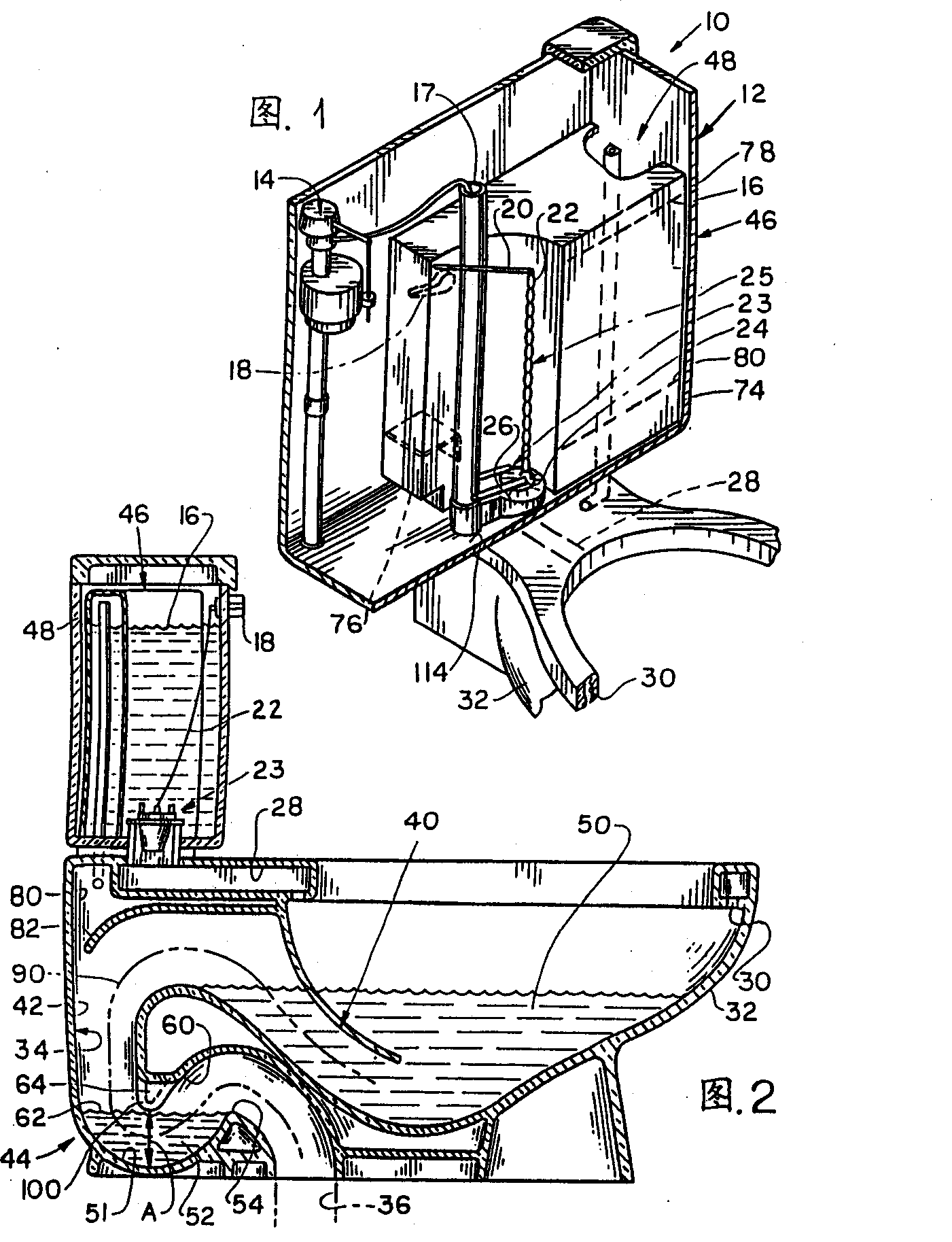
[0028] Figure 1 depicts a vacuum assisted toilet 10 which includes a tank or sink 12 which holds a conventional inlet valve 14 . The water inlet valve distributes water to the water tank until the water level reaches a predetermined high water level 16, and it also distributes water through a refill pipe 17 to the toilet. When a handle 18 of the flushing valve assembly 25 is pressed by hand to rotate around the axis, a bar 20 and a chain 22 are lifted to operate a drain valve 23 by rotating a drain valve assembly 24 to make it This is done by lifting away from a seat 26 of the discharge valve which faces mainly upwards. The water in the water tank flows quickly through the seat 26 and a water channel 28 and through the toilet side orifice 30 and enters the toilet 32 ​​(the toilet seat is not shown). As shown in Figure 2, the toilet 32 ​​has a toilet outlet 34 which discharges water and waste into a sewer 36 which is connected to the sewage system.

[0029]The toilet outlet 3...


PUM


Abstract

A vacuum assisted toilet in which a vacuum is applied between the upper and lower curves of the toilet outlet during flushing, the down lane is made to more reliably ensure that an air channel (64) is in a pool of water in the lower curve ( 52) above, it can be closed quickly near the start of a flush, and it remains open when not flushing. The lower bend has a lower wall (51), which maintains a pool of water (52), maintains a pool roof (62) at a predetermined height (A) between flushing intervals, and has an upper wall positioned above the pool roof (60) to form an air channel. The upper wall forms a vent (100) for a narrow and high air passage.

Description

technical field [0001] This invention relates to toilets, and more particularly to a vacuum assisted toilet. Background technique [0002] Applicant's US Patent 5,142,712 describes a vacuum assisted toilet where a vacuum is applied during flushing of the toilet so that less water is used to complete a complete flush. The outlet of the toilet includes a lower bend except the usual upper bend, and a bend passage is arranged between the two bends. Vacuum is applied to the bend path near the start of flushing. The lower bend includes a lower wall, which accommodates a tank of water, and an upper wall above the water surface to keep a gap between the two to form an air passage. During the time between flushes, the air passage must be open so that all the water in the toilet is not siphoned away. On the other hand, the lower trap must close the air passage soon after flushing begins, so that the vacuum applied to the trap passage can assist in the extraction of the toilet conte...

Claims


Application Information

Patent Timeline
Patent Type & Authority Patents(China)
IPC IPC(8): E03D11/06E03D11/13E03D5/00E03D11/18
CPCE03D5/00E03D11/18Y10T137/4576Y10T137/4531
Inventor 阿诺德·亨尼西
Owner FLUIDMASTER
Why Eureka
Try Eureka