
A real-time filtering system and method for random noise of a MEMS gyroscope

A random noise and gyroscope technology, applied in the field of inertial navigation, can solve the problems of poor measurement accuracy, poor real-time performance and stability, and inability to obtain gyroscopes, and achieve the effect of solving inconsistent noise characteristics

Active Publication Date: 2018-12-21
BEWIS TECH
View PDF6 Cites 7 Cited by
  • Summary
  • Abstract
  • Description
  • Claims
  • Application Information

AI Technical Summary

Problems solved by technology

However, in practical application scenarios, the gyroscope is often in a complex motion mode, but in the system equation, the estimated value of the true value X(t)=X(t-1), so the estimated value of the true value and the actual state of motion are always will be delayed by one time unit
Due to the high sampling frequency of the gyroscope chip, the delay has almost no effect on the estimated value X(t) during steady state and slow speed-changing motions. , the estimated value X(t) is very different from the real value, resulting in obvious delay effect, and the solutions for complex motion patterns in the prior art cannot take into account both accuracy and following ability, resulting in complex motion patterns, the gyroscope The measurement accuracy is very poor
[0033] 3. The measurement noise R is an important parameter that affects the performance of the Kalman filter. An inappropriate value will affect the filter effect and even cause the filter to diverge. However, the prior statistical characteristics of the measurement noise are difficult or impossible to obtain. For this Problem, many adaptive filters have been proposed and adopted, such as Sage-Husa adaptive filter algorithm, particle filter algorithm, although they can achieve good results, but with a large number of matrix operations, large amount of calculation, poor real-time performance and stability

Method used


Image

  • A real-time filtering system and method for random noise of a MEMS gyroscope
  • A real-time filtering system and method for random noise of a MEMS gyroscope
  • A real-time filtering system and method for random noise of a MEMS gyroscope

Examples


Embodiment Construction

[0097] The specific implementation manner of the present invention will be described below in conjunction with the accompanying drawings.

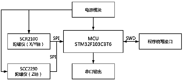
[0098] like figure 1 Shown is a schematic diagram of the hardware structure of the present invention, the power module is electrically connected to the MEMS gyroscope and the microprocessor MCU, the MEMS gyroscope includes a gyroscope for measuring X / Y axis signals and a gyroscope for measuring Z axis signals, and the gyroscope and MCU Connected through the signal line, the original signal measured by the gyroscope is input to the MCU and filtered by the algorithm module inside the MCU, and the filtered signal is output in real time through the serial port. The MCU is also connected with a program writer interface for writing the filter to the MCU. Algorithmic programs required.

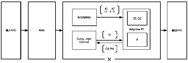
[0099] like figure 2 Shown is a schematic diagram of the algorithm module of the present invention, the algorithm module of the present invention is integrate...


PUM


Abstract

The invention discloses a real-time filtering system for random noise of a MEMS gyroscope, comprising a MEMS gyroscope and a microprocessor MCU, wherein the gyroscope and the MCU are connected througha signal line. The algorithm module includes AMA module and FAKF filter. The FAKF filter comprises an RLS module, a FLC module and an AKF module. The real-time filtering method of the invention adopts the improved RLS to fit the coefficients of the ARMA time series model, and updates the coefficients a1, a2, c1 and sigma 2 in the obtained gyroscope noise series in realtime, thereby effectively solving the problem that the noise model in the off-line model is inconsistent with the noise characteristic after long-time movement. The invention adopts the AMA method to detect the sudden change point in the gyroscope motion process, adopts the smaller Qi value for the steady-state motion state to improve the precision, and adopts the larger Qi value for the violent change acceleration motion state to improve the following ability of the gyroscope to the motion, and solves the problems of the dynamic motion precision and the following ability.

Description

technical field [0001] The invention relates to the technical field of inertial navigation, in particular to a system and method for real-time filtering of MEMS gyroscope random noise in practical application scenarios. Background technique [0002] MEMS gyroscope is a kind of inertial measurement unit that uses MEMS (Micro Electro-Mechanical System) technology to measure the angular rate of object motion. It is the core of Attitude Heading Reference System (AHRS) and Micro-Inertial Navigation System (Micro-INS) device. Because of its small size, light weight, low cost, and good reliability, attitude sensors with low-end performance and single MEMS devices have been widely used in mountain slopes, building bridges, engineering facilities, aircraft, vehicles, and human bodies. Attitude monitoring has good economic and social benefits, and high-precision MEMS gyroscopes are used in defense fields such as drones and precision-guided weapons. With the in-depth application of M...

Claims


Application Information

Patent Timeline
IPC IPC(8): H03H21/00G01C21/16G01C19/00
CPCH03H21/0025H03H21/0043G01C19/00G01C21/16
Inventor 时广轶蒋晓伟马力
Owner BEWIS TECH
Learn More