
Wire binding device and automatic wire binding equipment

A wire tie device and equipment technology, applied in the field of wire tie devices and automatic wire tie equipment, can solve problems such as inconvenient construction, time-consuming, labor-intensive, dangerous, etc., to reduce the time of tie wire, reduce the risk, and save manpower Material effect

Pending Publication Date: 2018-12-21
GUANGDONG POWER GRID CO LTD +1
View PDF0 Cites 4 Cited by
  • Summary
  • Abstract
  • Description
  • Claims
  • Application Information

AI Technical Summary

Problems solved by technology

It is time-consuming and labor-intensive, and it is very inconvenient for the staff to work at high altitudes, and there is a certain degree of danger

Method used


Image

  • Wire binding device and automatic wire binding equipment
  • Wire binding device and automatic wire binding equipment
  • Wire binding device and automatic wire binding equipment

Examples


Embodiment Construction

[0031] In order to make the purpose, technical solutions and advantages of the embodiments of the present invention clearer, the technical solutions in the embodiments of the present invention will be clearly and completely described below in conjunction with the drawings in the embodiments of the present invention. Obviously, the described embodiments It is a part of embodiments of the present invention, but not all embodiments. The components of the embodiments of the invention generally described and illustrated in the figures herein may be arranged and designed in a variety of different configurations.

[0032] Accordingly, the following detailed description of the embodiments of the invention provided in the accompanying drawings is not intended to limit the scope of the claimed invention, but merely represents selected embodiments of the invention. Based on the embodiments of the present invention, all other embodiments obtained by persons of ordinary skill in the art wi...


PUM


Abstract

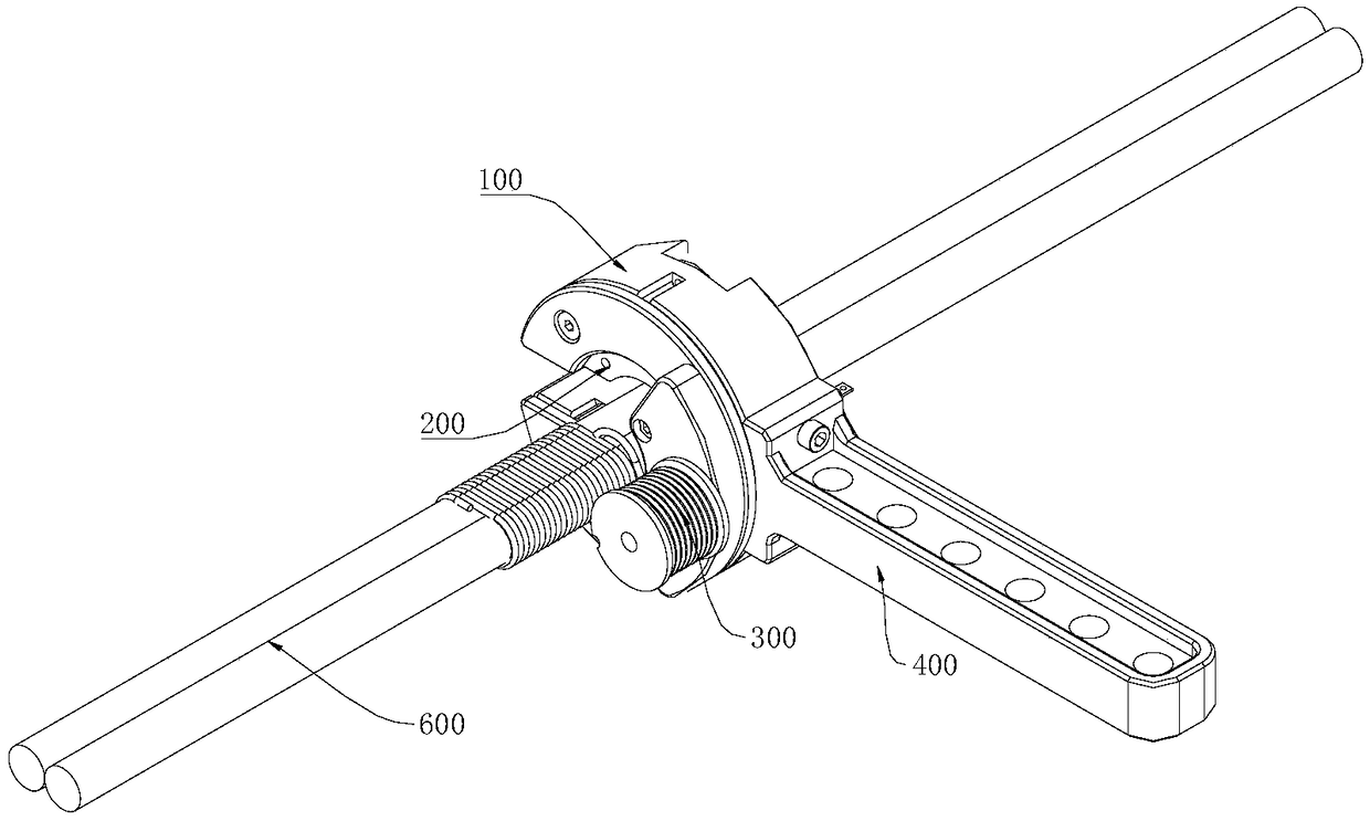
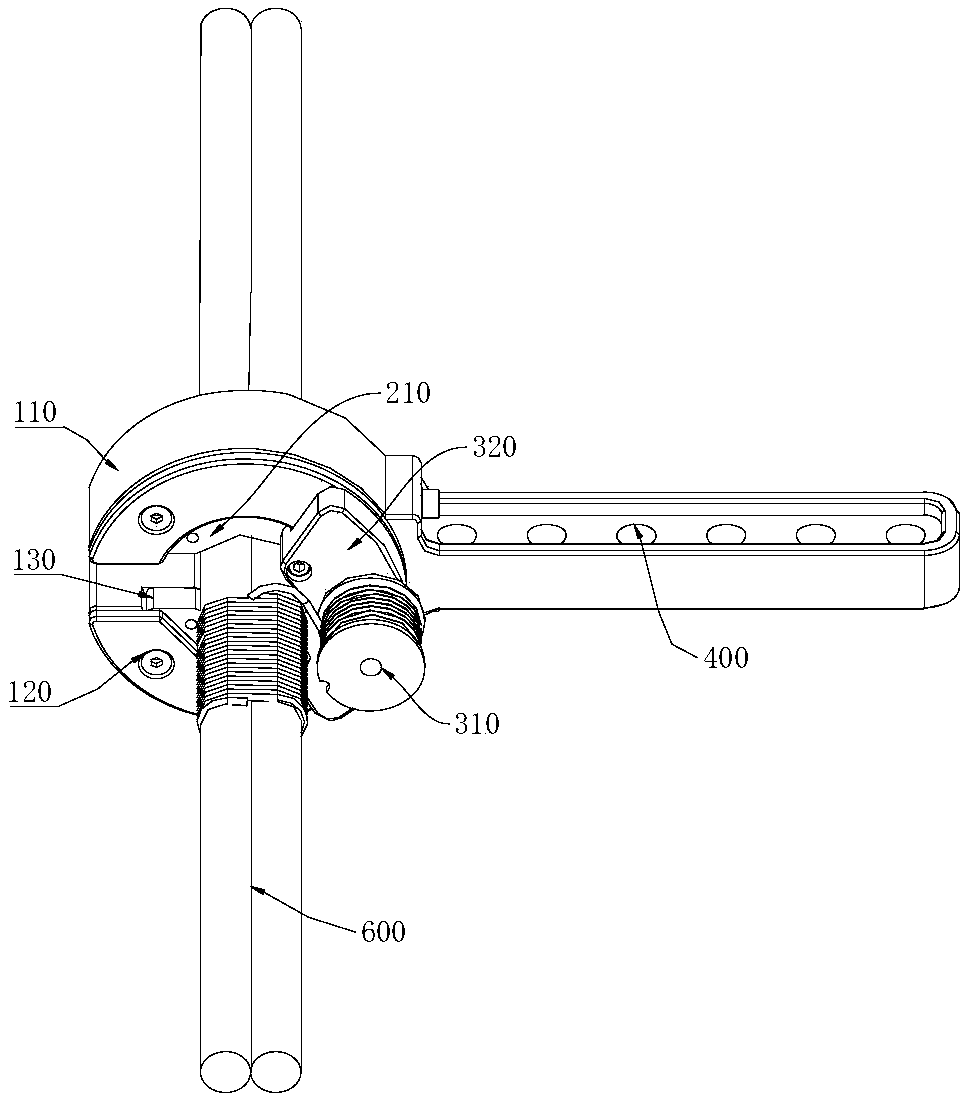
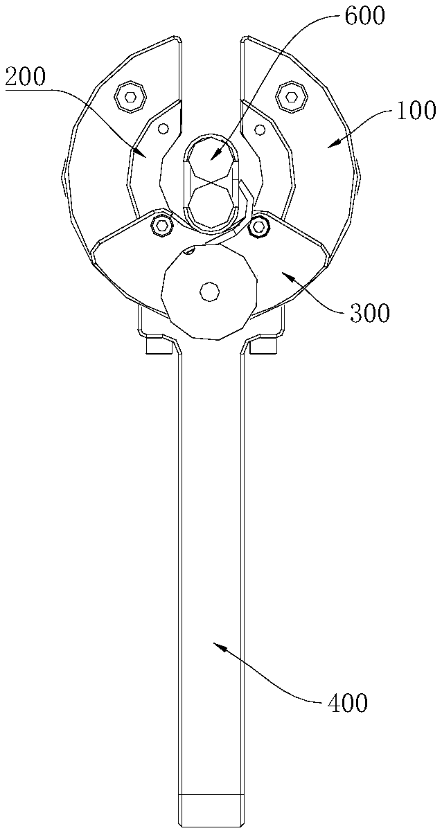
The invention relates to a wire binding device and an automatic wire binding device, belonging to the technical field of wire binding. The wire binding device comprises a main body, a rotating body and a winding device, A cavity is arranged in the main body, a rotating body is arranged in the cavity and can rotate relative to the main body, the main body and the rotating body are both provided with a notch allowing the target object to pass through, a wire winding device is provided with a wire, the wire winding device is connected with the rotating body, and the wire binding device can be driven by the rotating body to rotate around the target object so as to bind the wire to the target object. The wire binding device is used to bind the harder to move and longer object. The automatic wire binding device comprises an electric motor and the wire binding device. The rotating body is connected with the electric motor and driven to rotate by the electric motor. The automatic wire bindingdevice realizes that the wire binding of the wire winding device is wound on the target object one turn at a time through the rotation of the rotating body driven by the motor, which is very convenient, improves the wire binding efficiency of the insulated overhead conductor, saves manpower and material resources, reduces the wire binding time of the staff, and reduces the risk of wire binding athigh altitude.

Description

technical field [0001] The invention relates to the technical field of binding wires, in particular to a wire binding device and automatic binding equipment. Background technique [0002] The traditional technique for binding insulated overhead conductors is that workers use multi-strand aluminum wires to wind multiple insulated conductors in circles. It is time-consuming and labor-intensive, and it is very inconvenient for the staff to work at high altitudes, and there is a certain degree of danger. Contents of the invention [0003] The purpose of the present invention is to provide a wire binder for binding long and difficult moving target objects. [0004] Another object of the present invention is to provide an automatic thread binding device, which can realize automatic thread binding and is very convenient. [0005] Embodiments of the present invention are achieved like this: [0006] A wire binding device for binding target objects, which includes a main body, a...

Claims


Application Information

Patent Timeline
IPC IPC(8): H02G1/02B65B27/06B65B13/02
CPCH02G1/02B65B13/02B65B27/06
Inventor 麦嘉颖范伟波韦颖康叶露苏欢欢侯浩贤张博梁健亮区婉媚
Owner GUANGDONG POWER GRID CO LTD
Learn More