
A substation cabinet dehumidify device

A transformer cabinet and package technology, applied in the field of transformer cabinets, can solve problems such as humidity in the transformer cabinet, affecting the life and use of the transformer cabinet, and the inability to dehumidify and dry the transformer cabinet, and achieve convenient operation, simple structure, and mobile effect good effect

Pending Publication Date: 2018-12-21
TIANJIN KEYSINO NEW ENERGY ELECTRICAL
View PDF5 Cites 2 Cited by
  • Summary
  • Abstract
  • Description
  • Claims
  • Application Information

AI Technical Summary

Problems solved by technology

[0003] The transformer cabinet is an indispensable equipment. The transformer cabinet will be wet due to long-term use and improper placement due to the influence of the weather, which will affect the life and use of the transformer cabinet. The existing transformer cabinet cannot dehumidify and dry itself. In order to To solve this problem, it is necessary to design a dehumidification device for the transformer cabinet

Method used


Image

  • A substation cabinet dehumidify device
  • A substation cabinet dehumidify device
  • A substation cabinet dehumidify device

Examples


Embodiment Construction

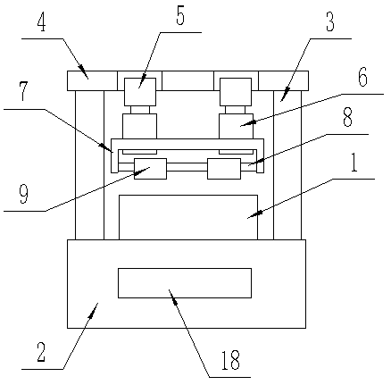
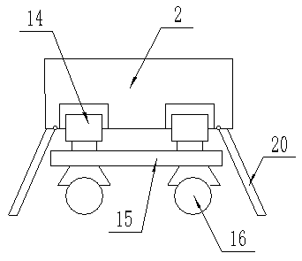
[0016] The present invention will be described in detail below with reference to the drawings, such as Figure 1-3 As shown, a dehumidification device for a substation cabinet includes a substation cabinet body 1, a rectangular casing 2 is provided on the lower surface of the substation cabinet body 1, and support rods 3 are provided on both sides of the upper surface of the rectangular casing 2 Each of the support rods 3 is jointly fixed and connected to the support plate 4, the lower surface of the support plate 4 is machined with a pair of rectangular grooves, and each of the rectangular grooves is embedded with a No. Motor 5, each of the No. 1 miniature rotating motors 5 is fixedly connected with a rotating rod 6 on the rotating end, each of the rotating rods 6 is jointly sleeved with a rotating frame 7, and the rotating frame 7 is fixedly connected with a rotating shaft 8. A pair of micro-drying fans 9 are fitted on the rotating shaft 8, a circular groove is machined at th...


PUM


Abstract

A substation cabinet dehumidify device includes a transformer cabinet body, A lower surface of that transformer cabinet body is provided with a rectangular shell, A support rod is arranged on both sides of the upper surface of the rectangular shell, A support plate is fixedly connected to each of the support rods, A lower surface of the support plate is machined with a pair of rectangular groove,Each of the rectangular grooves is fitted with a No. 1 micro-rotating electric machine with the rotating end downward, and each of the No. 1 micro-rotating electric machines is fixedly connected witha rotating rod, and each of the rotating rods is provided with a rotating frame, wherein the rotating frame is fixedly connected with a rotating circular shaft, and the rotating circular shaft is provided with a pair of micro-drying fans. The invention has the advantages of simple structure, convenient operation, dehumidification, good dehumidification effect, good moving effect and convenient moving.

Description

Technical field [0001] The invention relates to the field of substation cabinets, in particular to a dehumidification device for substation cabinets. Background technique [0002] The transformer cabinet is to change the high voltage to low, or to change the low voltage to high. According to the load requirements, the electricity is arranged. The three-phase four-wire system is distributed in the power distribution cabinet to meet the equipment use requirements, and some electrical needs 380V , Some need 220V, and some devices need to be started directly. [0003] The substation cabinet is an indispensable device. The substation cabinet will be wet due to long-term use and improper placement due to the influence of the weather, which will affect the life and use of the substation cabinet. The existing substation cabinet cannot dehumidify and dry itself. To solve this problem, it is necessary to design a dehumidification device for the transformer cabinet. Summary of the invention...

Claims


Application Information

Patent Timeline
Patent Type & Authority Applications(China)
IPC IPC(8): H02B1/30H02B1/28H02B1/56B01D53/26
CPCB01D53/261H02B1/28H02B1/30H02B1/565B01D2257/80
Inventor 范霖君
Owner TIANJIN KEYSINO NEW ENERGY ELECTRICAL
Learn More