
A power-on device for a remote control

A technology of remote control and electrical devices, which is applied to circuits, electrical components, secondary batteries, etc., which can solve the problems of low detection efficiency, slow power-on speed, and high labor intensity, so as to improve detection efficiency and power-on speed , to avoid the effect of power-on and power-off

Inactive Publication Date: 2018-12-21
GREE ELECTRIC APPLIANCES WUHAN +1
View PDF6 Cites 2 Cited by
  • Summary
  • Abstract
  • Description
  • Claims
  • Application Information

AI Technical Summary

Problems solved by technology

[0003] However, the factory needs to carry out a large number of remote control button function testing work every day, and then needs to manually dismantle the battery to achieve the purpose of powering on the remote control. The speed of device remote control function detection. Therefore, in the prior art, there is a technical problem that the power-on speed is slow when the remote control function detection of electrical equipment is performed, resulting in low detection efficiency.

Method used


Image

  • A power-on device for a remote control
  • A power-on device for a remote control
  • A power-on device for a remote control

Examples


Embodiment Construction

[0029] In order to make the purpose, technical solutions and advantages of the embodiments of the present invention clearer, the technical solutions of the present invention will be clearly and completely described below in conjunction with the drawings in the embodiments of the present invention. Obviously, the described embodiments are the embodiment of the present invention Some embodiments of the technical solution, but not all embodiments. Based on the embodiments described in the present application documents, all other embodiments obtained by persons of ordinary skill in the art without creative efforts fall within the protection scope of the technical solution of the present invention.

[0030] In the specific practice process, after the remote control is assembled online, it is necessary to manually detect the key functions of the remote control, and the premise of the detection is to power on the remote control to be tested. Activate the function in the remote contro...


PUM


Abstract

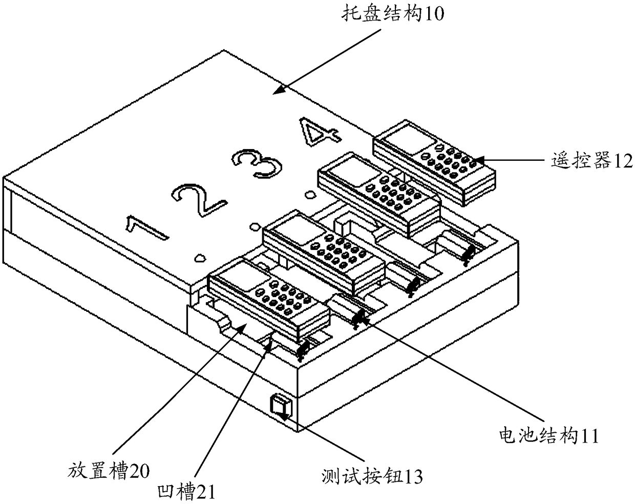
The invention discloses a power-on device of a remote controller, comprising a tray structure: a placing groove is arranged on the tray structure, and the placing groove is used for placing a remote controller to be tested; a battery structure: the battery structure is installed in the placing groove, and the battery structure comprises a battery body, which is used for supplying electric power tothe remote controller; a telescopic structure: the telescopic structure is connect with the battery structure; wherein, when the remote controller is placed on the placing groove for testing, the positive and negative electrodes of the battery body are controlled to be butted with the positive and negative electrodes of the battery port of the remote controller by the telescopic structure, thereby supplying electric power to the remote controller; After the test of the remote controller is completed, the positive and negative electrodes of the battery body are controlled to be disconnected from the positive and negative electrodes of the battery port by the telescopic structure, thereby stopping the power supply to the remote controller.

Description

technical field [0001] The invention relates to the field of power-on detection of a remote controller, in particular to a power-on device for a remote controller. Background technique [0002] In order to ensure the factory quality of remote controllers for electrical equipment such as air conditioners and televisions, it is necessary to test the key functions of the remote controllers for electrical equipment before leaving the factory. In order to realize the above detection, it is necessary to firstly power on the remote controller of the electrical equipment. In the prior art, the remote control is powered on mainly by manually installing the battery into the battery port of the remote control, and then the function of the keys of the remote control is detected. [0003] However, the factory needs to carry out a large number of remote control button function testing work every day, and then needs to manually dismantle the battery to achieve the purpose of powering on t...

Claims


Application Information

Patent Timeline
Patent Type & Authority Applications(China)
IPC IPC(8): H01M10/44
CPCH01M10/441Y02E60/10
Inventor 汪开烽翟志强胡建辉康扬刘爽
Owner GREE ELECTRIC APPLIANCES WUHAN
Learn More