
Driving control circuit and robot

A technology for driving control circuits and driving motors, which is applied in the direction of program control and electrical program control in sequence/logic controllers, and can solve problems such as reducing the service life of the main board

Pending Publication Date: 2017-04-26
UBTECH ROBOTICS CORP LTD
View PDF12 Cites 4 Cited by
  • Summary
  • Abstract
  • Description
  • Claims
  • Application Information

AI Technical Summary

Problems solved by technology

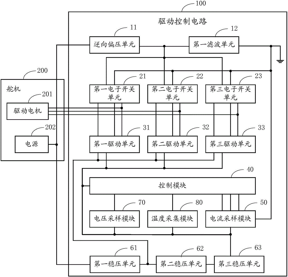
[0003] However, if the existing robots and automatic guided vehicles driven by the steering gear are artificially pulled after the steering gear is powered off, the driving motor of the steering gear will generate a directional electromotive force due to mechanical movement, and a small amount of current will be generated. The motherboard of the steering gear is powered on under abnormal conditions, which reduces the service life of the motherboard

Method used


Image

  • Driving control circuit and robot
  • Driving control circuit and robot
  • Driving control circuit and robot

Examples


Embodiment Construction

[0057] In order to enable those skilled in the art to better understand the solutions of the present invention, the technical solutions in the embodiments of the present invention will be clearly described below in conjunction with the accompanying drawings in the embodiments of the present invention. Obviously, the described embodiments are the embodiment of the present invention. Some examples, but not all examples. Based on the embodiments of the present invention, all other embodiments obtained by persons of ordinary skill in the art without creative efforts shall fall within the protection scope of the present invention.

[0058]The terms "comprising" and any variations thereof in the description and claims of the present invention and the above drawings are intended to cover non-exclusive inclusion. For example, a process, method or system, product or device comprising a series of steps or units is not limited to the listed steps or units, but optionally also includes st...


PUM


Abstract

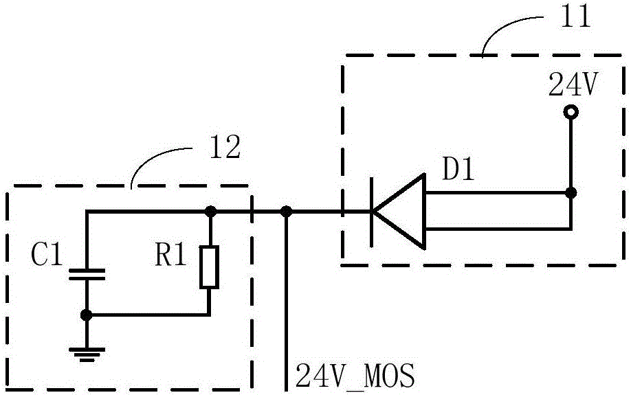
The invention provides a driving control circuit and a robot. The driving control circuit is used for driving the driving motor of a steering engine to move and comprises a reverse bias module, an electronic switch module, a driving module, a control module, a current sampling module and a voltage regulator module. The reverse bias module is accessed to the power supply of the steering engine and is connected to the electronic switch module. The driving module is connected to the driving motor through the electronic switch module. The control module is connected to the driving module and is connected to the electronic switch module through the current sampling module. The voltage regulator module is accessed to the power supply and then is connected to the driving module, the control module, and the current sampling module. The invention provides the driving control circuit comprising the reverse bias module, after the power cut of the steering engine, when the driving motor of the steering engine mechanically moves due to artificial pushing to generate back electromotive force, the current generated by the back electromotive force is prevented from flowing to the motherboard of the steering engine, and the power-on of the motherboard of the steering engine is avoided.

Description

technical field [0001] The embodiment of the invention belongs to the technical field of steering gear control, and in particular relates to a drive control circuit and a robot. Background technique [0002] With the continuous development of learnable technology, various automation equipment such as robots and automatic guided vehicles have been developed and applied to people's daily production and life, bringing great convenience to people's lives. Steering gear is widely used in automation equipment such as robots because of its advantages such as easy control, large torque, and mature manufacturing technology. [0003] However, if the existing robots and automatic guided vehicles driven by the steering gear are artificially pulled after the steering gear is powered off, the driving motor of the steering gear will generate directional electromotive force due to mechanical movement, and a small amount of current will be generated. The main board of the steering gear is p...

Claims


Application Information

Patent Timeline
IPC IPC(8): G05B19/04
CPCG05B19/04
Inventor 熊友军柳冬
Owner UBTECH ROBOTICS CORP LTD
Learn More