
Ocean wave force monitoring device

A monitoring device and wave force technology, which are applied to measuring devices, measuring fluid pressure, and measuring fluid pressure through electromagnetic components, etc., can solve the problems of damage reliability of balance sensitive components, complex structure of connecting parts, and complex structure of measuring components, etc. Avoid the effects of inaccurate monitoring, strong structural reliability and high sensitivity

Active Publication Date: 2018-01-26
OCEANOGRAPHIC INSTR RES INST SHANDONG ACAD OF SCI
View PDF6 Cites 5 Cited by
  • Summary
  • Abstract
  • Description
  • Claims
  • Application Information

AI Technical Summary

Problems solved by technology

In the existing balance force measurement method, since the sensitive element that feels the wave load is designed as a whole with the wave-bearing element (such as a cylinder), in order to ensure that the sensitive element can fully feel the load of ocean waves, the wave-bearing element is not connected without support. However, the structure of the connecting parts between the wave-bearing elements in the force measuring structure of the balance and the legs of the jacket of the offshore platform is very complicated; in addition, the entire balance has been connected with the legs of the jacket of the offshore platform before it is actually used. Debugging and calibration before measurement, it is easy to cause damage to the sensitive components of the balance and affect the reliability of the measurement parameters during the installation and construction of the offshore platform
Therefore, existing balance force measurement methods have defects such as complex structure of measuring components, high requirements for equipment installation, and low working reliability.

Method used


Image

  • Ocean wave force monitoring device
  • Ocean wave force monitoring device

Examples


Embodiment Construction

[0022] In order to make the purpose, technical solutions and advantages of the present invention clearer, the present invention will be further described in detail below in conjunction with the accompanying drawings. Obviously, the described embodiments are only some of the embodiments of the present invention, rather than all of them. Based on the embodiments of the present invention, all other embodiments obtained by persons of ordinary skill in the art without making creative efforts belong to the protection scope of the present invention.

[0023] The terms "first", "second", "third", "fourth", "fifth", "sixth", "seventh" and "Eighth" and the like, if present, are used to distinguish similar items and are not necessarily used to describe a particular order or sequence. It is to be understood that the data so used are interchangeable under appropriate circumstances such that the embodiments of the invention described herein are, for example, capable of practice in sequences...


PUM


Abstract

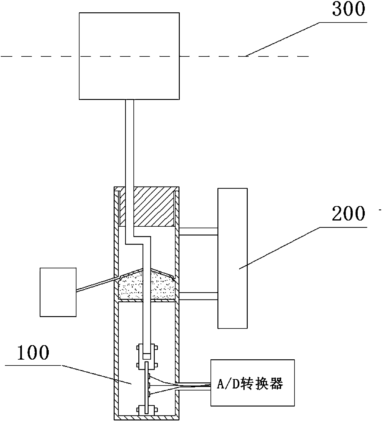
An ocean wave force monitoring device disclosed by the present invention belongs to the signal monitoring technology field, and comprises a buoyancy column, a guiding rod, a sealing head, a sleeve, adrying agent, a fixing support, a connecting clamp, an elastic film, a strain gauge, a signal line, an A / D converter and a water storage tank. When the ocean waves pass the buoyancy column, and underthe action of the buoyancy, the buoyancy column drives the guiding rod to move up and down in a sliding cavity and further drives the elastic film connected at the bottom to telescope. According to the ocean wave force monitoring device provided by the present invention, the strain gauge on the elastic film real-timely outputs the strain signals of the elastic film, and the A / D convert converts anelectric signal into a digital signal to transmit to the monitoring device. Moreover, the ocean wave force monitoring device provided by the present invention is convenient to install, is strong in structure reliability and high in sensitivity, can adapt to the complex ocean environments, can monitor the ocean wave environments, and provides the good monitoring means for the ocean engineering construction.

Description

technical field [0001] The invention relates to the technical field of signal monitoring, in particular to an ocean wave force monitoring device. Background technique [0002] The load that ocean waves act on the jacket of an offshore platform is one of the important parameters for designing an offshore platform. In order to obtain the data of ocean wave load, people use various measurement methods to measure. At present, the measurement methods of ocean wave load are mainly divided into two types: pressure measurement and force measurement; among them, pressure measurement is to obtain the ocean wave load by re-integrating the pressure. , while force measurement is a direct measurement method. [0003] The force measurement method commonly used to measure ocean wave loads is the balance force measurement method. In this balance force measurement method, first, the sensitive element detects the force of the ocean wave through the wave bearing element, and then transmits the...

Claims


Application Information

Patent Timeline
Patent Type & Authority Applications(China)
IPC IPC(8): G01L9/00
Inventor 王雷王虎贾欣鑫李遵伟柴旭
Owner OCEANOGRAPHIC INSTR RES INST SHANDONG ACAD OF SCI
Learn More