Engine cleaning method and device

A technology for cleaning devices and engines, which is applied to engine components, machines/engines, mechanical equipment, etc., and can solve problems such as slow circulation of cleaning oil

Active Publication Date: 2018-12-21
北京天元陆兵汽车科技有限公司
View PDF6 Cites 5 Cited by
  • Summary
  • Abstract
  • Description
  • Claims
  • Application Information

AI Technical Summary

Problems solved by technology

[0008] The purpose of the present invention is to provide an engine cleaning method and device to solve the technical problem that the cleaning oil circulates slowly inside the engine when cleaning the engine in the prior art

Method used


Image

  • Engine cleaning method and device
  • Engine cleaning method and device
  • Engine cleaning method and device

Examples


Embodiment Construction

[0027] In order to make the purpose, technical solution and advantages of the present invention clearer, the technical solution of the present invention will be described in detail below. Apparently, the described embodiments are only some of the embodiments of the present invention, but not all of them. Based on the embodiments of the present invention, all other implementations obtained by persons of ordinary skill in the art without making creative efforts fall within the protection scope of the present invention.

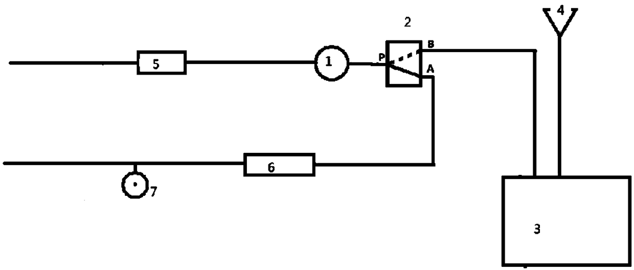
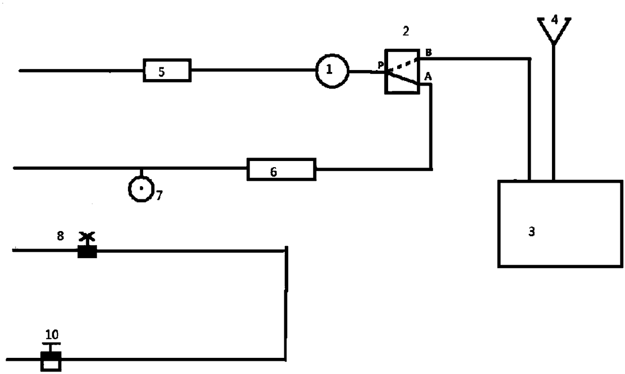
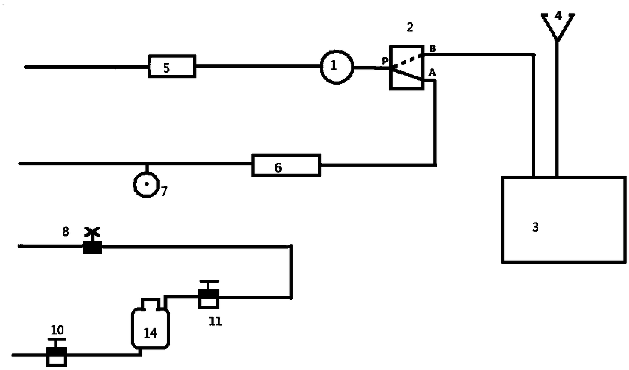
[0028] The invention provides a method for cleaning an engine, comprising the following steps: first step: when the engine is not started, use a hydraulic pump 1 to pump out the old engine oil in the oil pan at the bottom of the engine; second step: when the engine is not started Next, open the oil outlet of the lubricating oil passage of the engine, and use the gravity of the oil to empty the old engine oil inside the engine; Step 3: When the engine is not star...


PUM


Abstract

The invention provides an engine cleaning method and device and relates to the technical field of vehicle maintenance. The technical problem that cleaning oil flows circularly slowly in the engine when an engine is cleaned is solved. The engine cleaning device comprises a hydraulic pump, a two-position three-way reversing valve, an old oil bucket and a receiving disc. The hydraulic pump is locatedbetween an oil pan of a cleaned vehicle and the two-position three-way reversing valve. When the two-position three-way reversing valve keeps oil way connection of the hydraulic pump and an engine oil tank of the cleaned vehicle, an engine external cleaning loop is formed. The receiving disc and an engine lubricating oil way outlet are connected for receiving waste engine oil flowing out of the engine, and the bottom of the receiving disc communicates with the old oil bucket. The hydraulic pump works to facilitate acceleration circular flowing of the cleaning oil in a vehicle lubricating oilway. The engine cleaning method and device are used for cleaning and maintenance of the vehicle engine.

Description

technical field [0001] The invention relates to the technical field of vehicle maintenance, in particular to an engine cleaning method and device. Background technique [0002] Modern automobile engine design is very sophisticated, which reduces the degree of environmental pollution, improves fuel combustion efficiency, and prolongs the life of the engine, but at the same time, the requirements for the cleanliness of engine oil, oil additives and the engine itself are also greatly improved. [0003] When the engine is in good condition, it provides sufficient power with economical fuel consumption according to design requirements. However, after a period of operation, harmful substances such as carbon deposits and gums will be produced in the engine, which will slowly accumulate into sludge. It will increase the fuel consumption of the engine, reduce the power, fail to meet the precise matching clearance requirements of the engine, and even cause damage to the engine in sev...

Claims


Application Information

Patent Timeline
Patent Type & Authority Applications(China)
IPC IPC(8): F02B77/04
CPCF02B77/04
Inventor 程晓杰
Owner 北京天元陆兵汽车科技有限公司
Why Eureka
Try Eureka