Simple stretched iron wire binding device

A binding device and wire technology, applied in the direction of transmission elements or pulley ropes or cables, textile cables, building types, etc., can solve the problems of wire cutter jaw wear, damage to the galvanized protective layer on the surface of the wire, and the quality of wire binding. , to avoid the wear of the jaws, ensure the quality of the binding, and improve the efficiency of the binding

Pending Publication Date: 2018-12-21
眉山市三新供电服务有限公司
View PDF0 Cites 6 Cited by
  • Summary
  • Abstract
  • Description
  • Claims
  • Application Information

AI Technical Summary

Problems solved by technology

[0004] The purpose of the present invention is to provide a simple wire tying wire for the problems that the quality of the wire tying is likely to occur when the wire pliers are used to bind the wire, and the jaws of the wire pliers will be severely worn and the galvanized protective layer on the surface of the wire will be damaged. Binding device, the binding device can make the iron wire binding tightly and firmly, ensuring the binding quality of the pull wire iron wire, and at the same time not damaging the galvanized layer on the surface of the iron wire, avoiding the wear of the jaws of the wire pliers, improving the service life of the wire pliers, and improving the binding efficiency of the pull wire iron wire

Method used


Image

  • Simple stretched iron wire binding device
  • Simple stretched iron wire binding device
  • Simple stretched iron wire binding device

Examples


Embodiment

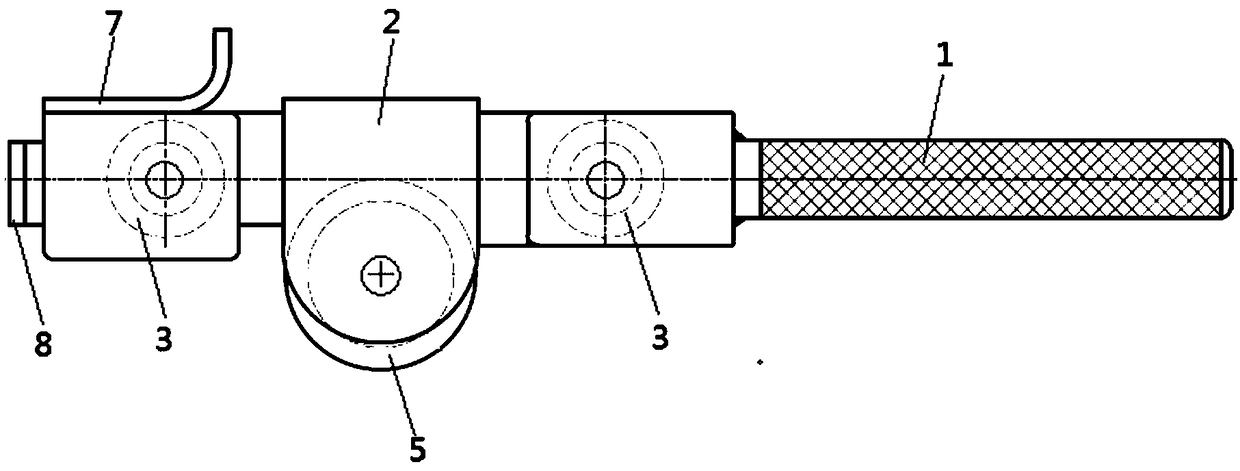
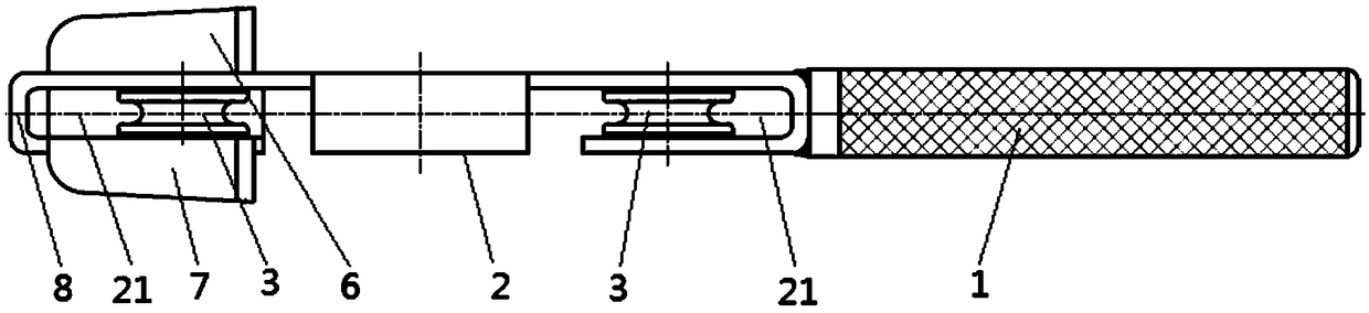
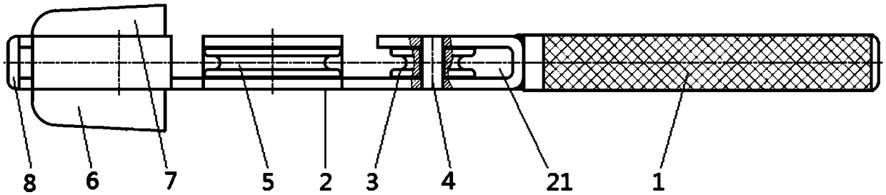
[0030] This embodiment provides a simple and simple stay wire binding device;

[0031] Such as Figure 1-Figure 3 As shown, the simple guy wire binding device in this embodiment includes a pliers main body 2 and a handle 1 connected to the rear thereof. The pliers main body is provided with three wire wheels arranged at intervals, and the wire wheels can freely move on the pliers main body. Rotating, the wire wheel is provided with an annular groove for limiting the iron wire, and the front part of the pliers main body is also provided with an L-shaped support plate for supporting the pull wire during binding.

[0032] In the present invention, by setting the main body of the pliers and the handle connected to the rear part, three wire wheels arranged at intervals are arranged on the main body of the pliers, and the wire wheels can rotate freely on the main body of the pliers. Ring groove, the front part of the pliers body is also equipped with an L-shaped support plate for s...


PUM


Abstract

The invention discloses a simple stay wire and iron wire binding device. The device comprises a clamp body and a handle connected with the rear portion of the clamp body, three wire wheels are disposed on the clamp body at intervals, and the wire wheels can freely rotate on the clamp body; annular grooves used for limiting iron wires are formed in the wire wheels, and an L-shaped supporting plateused for supporting stay wires during binding is further arranged at the front part of the clamp body. According to the binding device, the problems that excessively large force is needed during binding and zinc-plated layers on the surfaces of the iron wires are easy to damage are solved, the iron wires can have proper binding force, and the surfaces are kept smooth and free of damage. The binding device make the iron wires tightly and firmly bound, the binding quality of the stay wires and the iron wires is guaranteed, and meanwhile, the zinc-plated layers on the surfaces of the iron wires are not damaged; abrasion of a steel wire clamp jaw is avoided, the service life of the steel wire clamp is prolonged, and the stay wire and iron wire binding efficiency can be improved.

Description

technical field [0001] The invention relates to the technical field of electric power construction, in particular to a simple guy wire binding device. Background technique [0002] The purpose of the pull wire is to balance the force of all aspects of the pole and resist the wind pressure to prevent the pole from toppling over. Therefore, the pull wire is a guarantee measure for the safe erection and operation of the line that cannot be ignored. Install. [0003] During the production process of the pull wire, it is necessary to connect the pull wire with the wire clip. Specifically, after the steel strand is inserted into the wire clip, the head of the steel strand is bent to form a thread end, and then the thread end is reversed into the wire clip, and finally the thread end is connected with the steel wire Twisted wires are bound tightly with iron wire. Traditional binding is to use steel wire pliers to clamp the iron wire, and then wrap and bind the steel strand contin...

Claims


Application Information

Patent Timeline
Patent Type & Authority Applications(China)
IPC IPC(8): E04H12/20F16G11/12
CPCE04H12/20F16G11/12
Inventor 余良清喻自建梁永超杨晓波王松徐中林胡料苓刘寿才杨映春
Owner 眉山市三新供电服务有限公司
Why Eureka
Try Eureka