
Pneumatic precipitation method and used precipitation device

A pneumatic and gas technology, used in construction, infrastructure engineering and other directions, can solve the problems of abandoned wells, high costs, and high well pipe construction costs, and achieve the effects of low construction cost, low equipment maintenance cost, and strong precipitation capacity.

Inactive Publication Date: 2018-12-21
张继红
View PDF4 Cites 0 Cited by
  • Summary
  • Abstract
  • Description
  • Claims
  • Application Information

AI Technical Summary

Problems solved by technology

Existing dewatering technologies all require well pipes, which are expensive to construct, and are often damaged during the excavation process, resulting in abandoned wells. In addition, during foundation floor construction, the well pipes need to be sealed due to the need for continuous dewatering to cause the well pipes to pass through the floor. Well treatment, high cost

Method used


Image

  • Pneumatic precipitation method and used precipitation device

Examples


Embodiment Construction

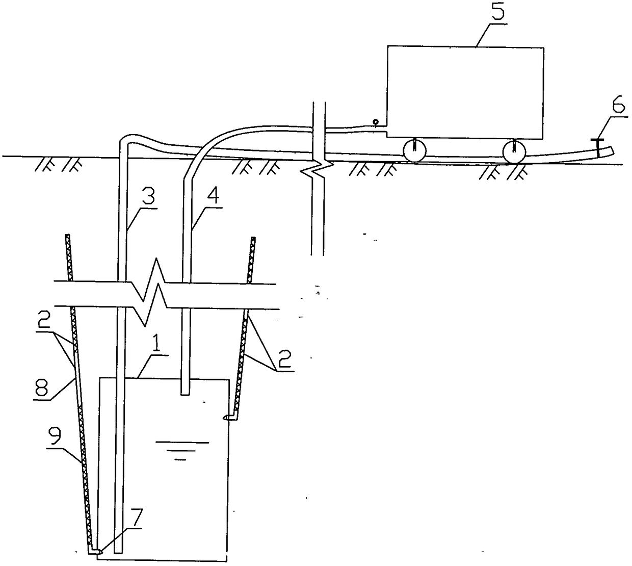
[0015] As an embodiment of the present invention, combined with figure 1 The mechanism and implementation method of the aerodynamic precipitation method and the aerodynamic precipitation device used in the present invention are introduced in detail. First, combine figure 1 The structure and working mechanism of the pneumatic precipitation device of the present invention are introduced. Such as figure 1 Shown, pneumatic precipitation device of the present invention comprises water storage tank (1), underground water collector (2), water outlet pipe (3), air delivery pipe (4), five parts of air delivery device (5), wherein water storage tank (1) is a container buried deep in the soil, and the groundwater collector (2) includes two parts, a water flow channel (8) and a filter membrane (9), wherein the water flow channel (8) is connected with the water storage tank (1), and the filter The membrane (9) is wrapped on the outside of the water flow channel (8), the groundwater coll...


PUM


Abstract

The invention relates to a pneumatic precipitation method and a used pneumatic precipitation device in the field of precipitation engineering. The pneumatic precipitation method comprises the following steps of: a, placing a water storage tank (1) with an underground water collector (2), a gas delivery pipe (4) and a water outlet pipe (3) in soil mass under the ground surface, and enabling one endof the water outlet pipe (3) to extend to the ground surface; b, collecting underground water into the water storage tank (1) by utilizing the underground water collector (2); c, inputting gas into the water storage tank (1) by the gas delivery pipe (4), and increasing a gas pressure in the water storage tank (1); and d, by utilizing a gas pressure difference between the gas pressure in the waterstorage tank (1) and a gas pressure on the ground surface, conveying accumulated water in the water storage tank (1) to the ground surface to drain so as to fulfill the aim of precipitation. According to the invention, pumping and precipitation of the underground water are implemented by air flow; and relative to a conventional precipitation device, the pneumatic precipitation device has the advantage that two key parts of a precipitation well pipe and a pumping device do not need to be arranged, so that construction cost is greatly reduced, and precipitation quality and efficiency are improved.

Description

technical field [0001] The present invention relates to the field of precipitation engineering in the field of geotechnical engineering. Background technique [0002] In the construction or maintenance of underground engineering, it is often accompanied by precipitation engineering, which facilitates engineering construction or maintenance by lowering the groundwater table or pressurized water head. For example, in the foundation pit project, it is often accompanied by the dewatering project. For example, in the anti-floating project, the groundwater table can be lowered by precipitation to reduce the buoyancy. In the leak plugging project, the water head difference of the leak can also be reduced by dewatering. Existing dewatering wells generally use well pipes for dewatering or light well point dewatering. The structure of dewatering wells generally includes three parts: well pipes, filter screens and filter materials. The well pipe is a tubular structure such as steel pi...

Claims


Application Information

Patent Timeline
Patent Type & Authority Applications(China)
IPC IPC(8): E02D19/10E02D19/20
CPCE02D19/10E02D19/20
Inventor 张继红
Owner 张继红
Learn More