
Hydraulic lifting process for installation of furnace shell during blast furnace overhaul

A technology of hydraulic lifting and blast furnace shell, which is applied to blast furnaces, blast furnace details, blast furnace parts, etc., can solve the problems of heavy overall weight and difficulty in hoisting, achieve the effects of improving stability and flexibility, speeding up progress, and ensuring construction quality

Active Publication Date: 2018-12-21
ANHUI MA STEEL EQUIP MAINTENANCE CO LTD
View PDF5 Cites 3 Cited by
  • Summary
  • Abstract
  • Description
  • Claims
  • Application Information

AI Technical Summary

Problems solved by technology

[0003] Aiming at the deficiencies in the background technology, the present invention provides a hydraulic lifting process for the installation of the furnace shell during the overhaul of the blast furnace. The application of the present invention can effectively solve the problem that the overall weight of the upper furnace shell is too large and difficult to hoist

Method used


Image

  • Hydraulic lifting process for installation of furnace shell during blast furnace overhaul
  • Hydraulic lifting process for installation of furnace shell during blast furnace overhaul

Examples


Embodiment 1

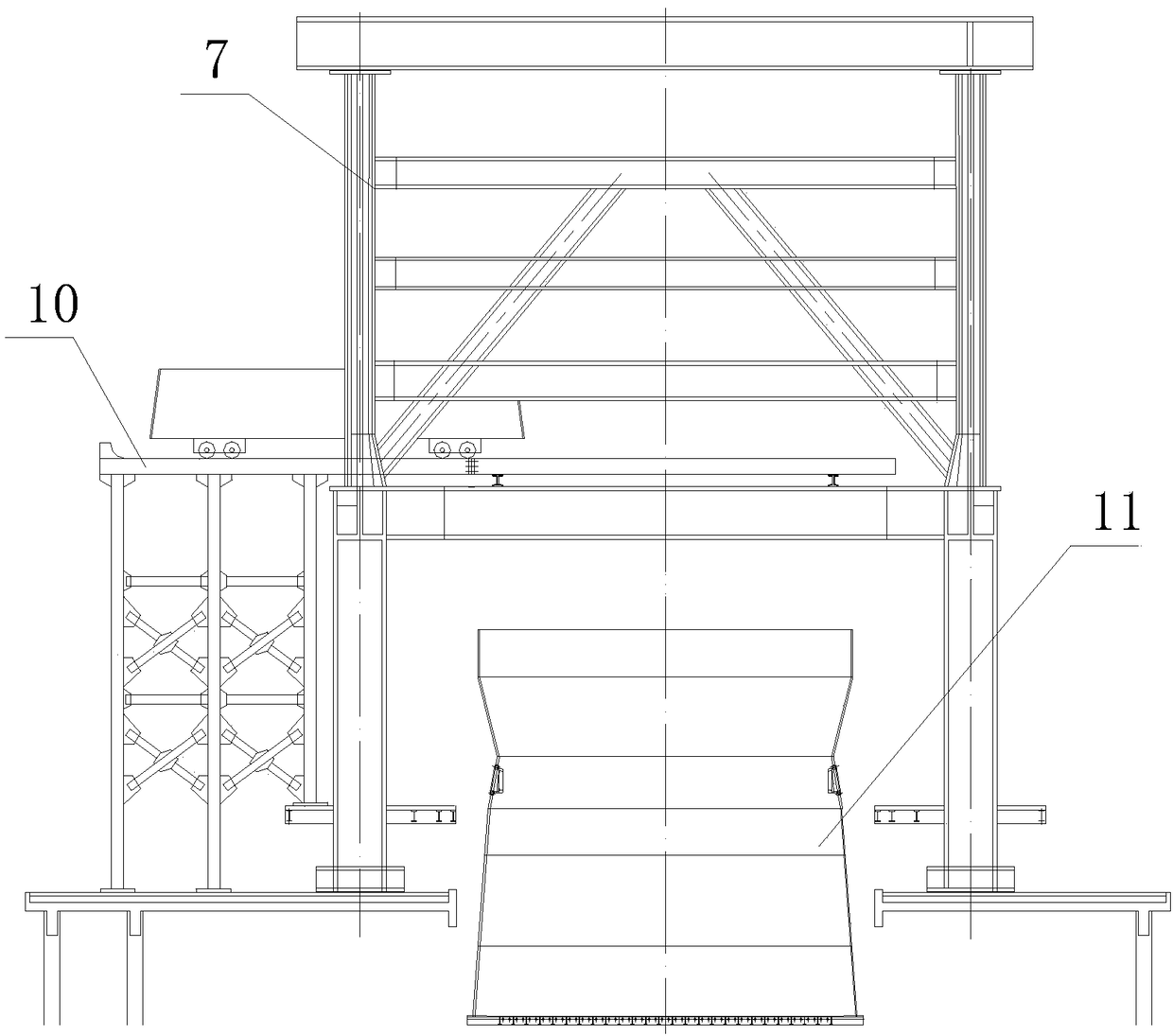
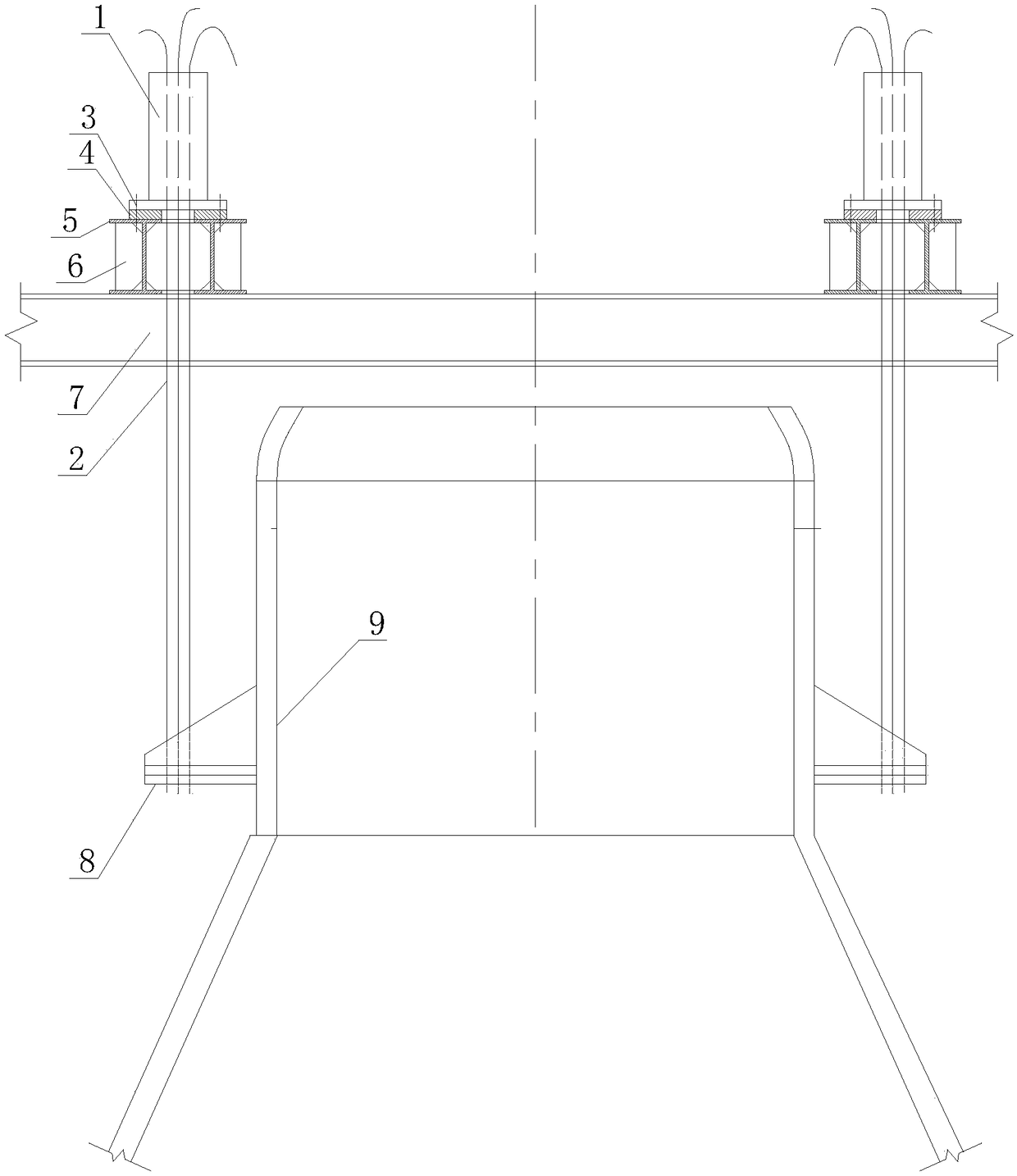
[0023] Such as figure 1 and figure 2 As shown, the present invention is a hydraulic lifting process for the installation of the blast furnace shell during the overhaul of the blast furnace, which is applied to the installation of the blast furnace shell during the overhaul of the blast furnace. During the overhaul of the blast furnace, the original furnace body frame 7 of the blast furnace is retained and set The temporary carriage platform 10 divides the blast furnace shell to be installed into an upper furnace shell 9 and a lower furnace shell 11. The lower furnace shells 11 are installed sequentially from bottom to top with each belt furnace shell. After the installation of the lower furnace shells 11 is completed, the upper furnace shells 9 are installed in a top-to-bottom sequence. For the inversion of each belt furnace shell, considering the structure of the furnace body frame 7 and the layout of the blast furnace casthouse, the temporary carriage platform 10 is genera...

Embodiment 2

[0031] Such as figure 1 and figure 2 As shown, take a certain steel with a 2500m 3 Taking a high-level blast furnace as an example, a hydraulic lifting process for the installation of the blast furnace shell during the overhaul of the blast furnace is applied to the installation of the blast furnace shell during the overhaul of the blast furnace. Temporary carriage platform 10 is set at the position, and the blast furnace shell to be installed is divided into upper furnace shell 9 and lower furnace shell 11. The upper furnace shell 9 is divided into 9-15 bands from bottom to top, and the lower furnace shell 11 is divided into 1-8 belts, the total weight of the upper furnace shell 9 is about 200t, and each belt furnace shell is translated from the temporary carriage platform 10 into the furnace body frame 7 and then hoisted and installed. The 1- The 8 belts all enter the furnace body frame 7 from the temporary carriage platform 10 in a complete circle, and are hoisted and in...


PUM

PropertyMeasurementUnit
heightaaaaaaaaaa

Abstract

The invention discloses a hydraulic lifting process for installation of a furnace shell during blast furnace overhaul. The hydraulic lifting process is used for installation of the furnace shell during blast furnace overhaul. An original furnace body frame is reserved. A temporary carriage platform is arranged in the middle portion of the furnace body frame. The blast furnace shell to be installedis divided into an upper furnace shell and a lower furnace shell. The upper furnace shell and the lower furnace shell are divided into a plurality of zones. The whole circle of each-zone furnace shell is translated into the furnace body frame from the temporary carriage platform and then is hoisted and installed. All the zones of furnace shells of the lower furnace shell are installed from bottomto top in sequence. After completion of installation of the lower furnace shell, the upper furnace shell is inversely installed from top to bottom in sequence. All the zones of furnace shells on theupper portion are hoisted through hydraulic continuous lifting jacks arranged on a girder of the top of the furnace body frame. Through the hydraulic lifting process, the problem that a furnace shellinversely installed is too large in integral weight and is hard to hoist can be effectively solved; lifting is stable and flexible, and the height is accurate; and the hydraulic lifting process can meet the requirements for integral lifting of the furnace shell, the blast furnace overhaul progress can be accelerated, and the construction quality can be ensured.

Description

technical field [0001] The invention is used in the field of electromechanical installation engineering, and relates to a hydraulic lifting process for installation of a furnace shell in the overhaul of a blast furnace, and is suitable for use when the furnace shell is installed in a full circle during the overhaul of a large blast furnace. Background technique [0002] During the overhaul of the blast furnace, it is generally necessary to replace part or all of the furnace shell, while the furnace body frame is retained, so that the blast furnace shell to be installed cannot be directly hoisted in place by a crane like when it is newly built. Generally, it is installed in pieces or in a full circle. If the furnace shell of a large blast furnace is installed in a full circle, due to the large diameter of the lower part of the furnace shell, it is generally impossible to fall into the furnace body frame from the furnace top. It is often necessary to enter from the middle of th...

Claims


Application Information

Patent Timeline
Patent Type & Authority Applications(China)
IPC IPC(8): C21B7/00
CPCC21B7/00
Inventor 晋杰章锐陈克胜周勇
Owner ANHUI MA STEEL EQUIP MAINTENANCE CO LTD
Learn More