
Sewage treatment process with aerating above liquid surface

A sewage treatment and liquid level technology, applied in water/sludge/sewage treatment, water aeration, aerobic process treatment, etc., can solve problems such as large air intake demand, large power consumption, and factory loss, and achieve reduction Electricity expenses, reducing operating costs, and the effect of reducing electricity expenses

Inactive Publication Date: 2018-12-21
罗亚宽
View PDF4 Cites 0 Cited by
  • Summary
  • Abstract
  • Description
  • Claims
  • Application Information

AI Technical Summary

Problems solved by technology

[0004] Disadvantages of the bottom exposure method: large power consumption, prone to clogging of micropores, and difficult maintenance and replacement of equipment
Due to the structural design of the bottom explosion method, if the oxygen contact surface is increased by reducing the exhaust hole to increase the oxygen utilization rate, the smaller the mesh, the sediment in the sewage will easily cause blockage, and the equipment is placed at the bottom of the sewage, and production must be stopped after blockage Water cut off for maintenance and replacement
[0005] The above-mentioned traditional bottom blasting method has uneven aeration, easy sludge deposition, and large demand for air intake, resulting in high energy consumption of equipment; it is a great loss to the factory

Method used


Image

  • Sewage treatment process with aerating above liquid surface
  • Sewage treatment process with aerating above liquid surface
  • Sewage treatment process with aerating above liquid surface

Examples


Embodiment 1

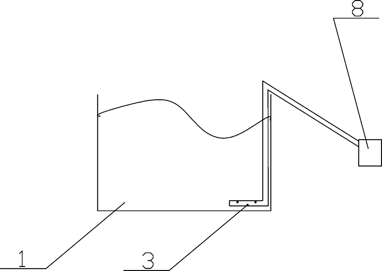
[0028] Such as Figure 5 As shown, the sewage treatment station has an aerobic sewage pool 1 with a total water volume of 600 cubic meters, sludge return flow of 30 cubic meters / h, and sewage incoming water of 30 cubic meters / h. The sewage contains high phosphate content (easy to cause pipe blockage). The existing aeration device is equipped with a 30-kilowatt blower fan 8 and adopts the bottom aeration method. It is understood that the current fan runs at full capacity throughout the day, and the water output index can only meet the discharge standard, which leads to huge energy consumption and increased expenses. That is to say, the amount of sewage per day is 30 cubic meters * 24 hours = 720 cubic meters. The electricity used in one day is 30 kilowatts * 24 hours = 720 kilowatts.

[0029] The bottom exposure method is that the fan 8 outside the sewage pool 1 passes the gas into the bottom of the sewage pool 1 through a pipeline, and sprays it out through the jet nozzle 3 ...

Embodiment 2

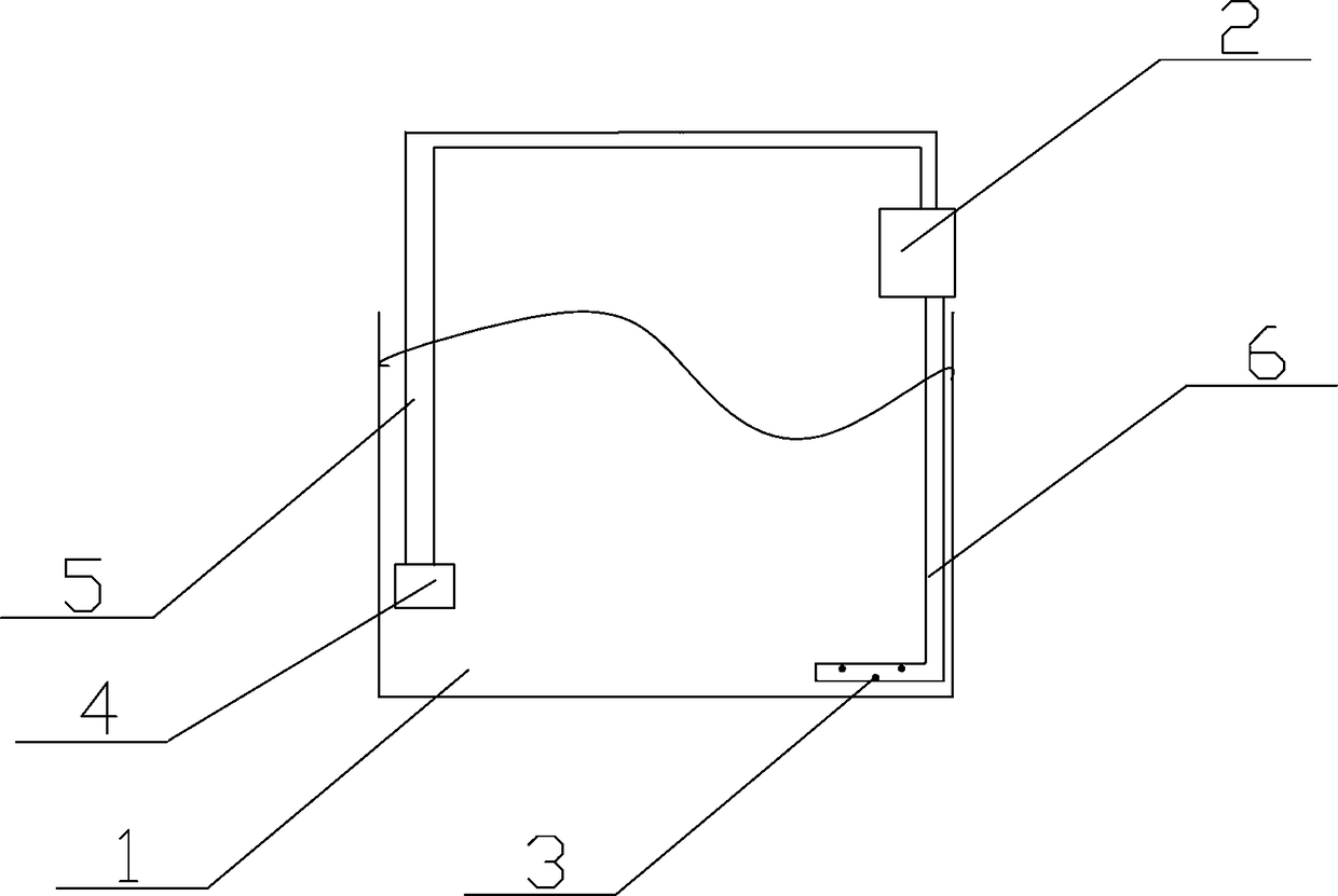
[0041] A sewage treatment process with aeration above the liquid level. The sewage oxygenation process includes: raising the sewage to 1.5 meters above the water surface, and then cooperating with the liquid level aerator 2 to fully integrate the sewage and air, and then hitting the bottom of the water through the jet nozzle 3 Squirt out.

[0042] Such as figure 2 and Figure 4 As shown, the device for the sewage oxygenation process includes a sewage pool 1, a water pump 4 is arranged in the sewage pool 1, the water pump 4 is located below the sewage liquid level, and an aerator 2 is arranged at 1.5 meters above the sewage liquid level , the top of the aerator 2 is connected to the water pump 4 through the suction pipe 5, the bottom of the aerator 4 is connected to the water delivery pipe 6, and the other end of the water delivery pipe 6 is provided with a jet nozzle 3, and the jet nozzle 3 is located in the sewage below the liquid level.

[0043] The aerator 2 includes a ...


PUM


Abstract

The invention relates to a sewage treatment process with aerating above a liquid surface. The sewage oxygenation process comprises steps of lifting sewage for 1-1.5 m above a water surface, fully mixing sewage and air by an aerator at 1-1.5 m above the water surface, then allowing the sewage mixed with air to reach a water bottom to spray out through a jet nozzle. The sewage treatment process improves the original sewage aeration method, is featured by aerating above the liquid surface, and is improved based on advantages of both traditional aeration and jet aeration, thereby being energy-saving, efficient and convenient.

Description

technical field [0001] The invention relates to the technical field of sewage treatment, in particular to a sewage treatment process for aeration above the liquid level. Background technique [0002] At present, the sewage aeration methods widely used in China are basically the bottom aeration method driven by Roots blower, and a very small number of them use "jet flow aeration". This method has the disadvantages of not obvious energy saving effect and high installation cost. less, no analysis here. [0003] Among them, the bottom aeration method includes disc-type microporous aeration, tube-type microporous aeration, etc., relying on the Roots blower to compress the air and pump it into the bottom of the sewage tank, and then use the bottom filter to release the air, and use the micropores to create small air bubbles. To achieve the effect of sewage oxygenation. [0004] Disadvantages of the bottom exposure method: high power consumption, prone to clogging of micropores, ...

Claims


Application Information

Patent Timeline
IPC IPC(8): C02F3/02C02F7/00
CPCC02F3/02C02F7/00Y02W10/10
Inventor 罗亚宽
Owner 罗亚宽
Learn More