Pipeline clamping device for vertical welding table

A technology of clamping device and welding table, which is applied in the direction of auxiliary devices, welding equipment, auxiliary welding equipment, etc., can solve the problems of large heat input, etc., and achieve the effect of stable welding quality, good effect and high production efficiency

Inactive Publication Date: 2018-12-21
OFFSHORE OIL ENG
View PDF6 Cites 2 Cited by
  • Summary
  • Abstract
  • Description
  • Claims
  • Application Information

AI Technical Summary

Problems solved by technology

Therefore, the high-efficiency hot wire tungsten argon arc welding all-position automatic horizontal welding process is used to solve the problem of excessive heat input

Method used


Image

  • Pipeline clamping device for vertical welding table
  • Pipeline clamping device for vertical welding table

Examples


Embodiment Construction

[0013] The present invention will be described in detail below in conjunction with the accompanying drawings and embodiments.

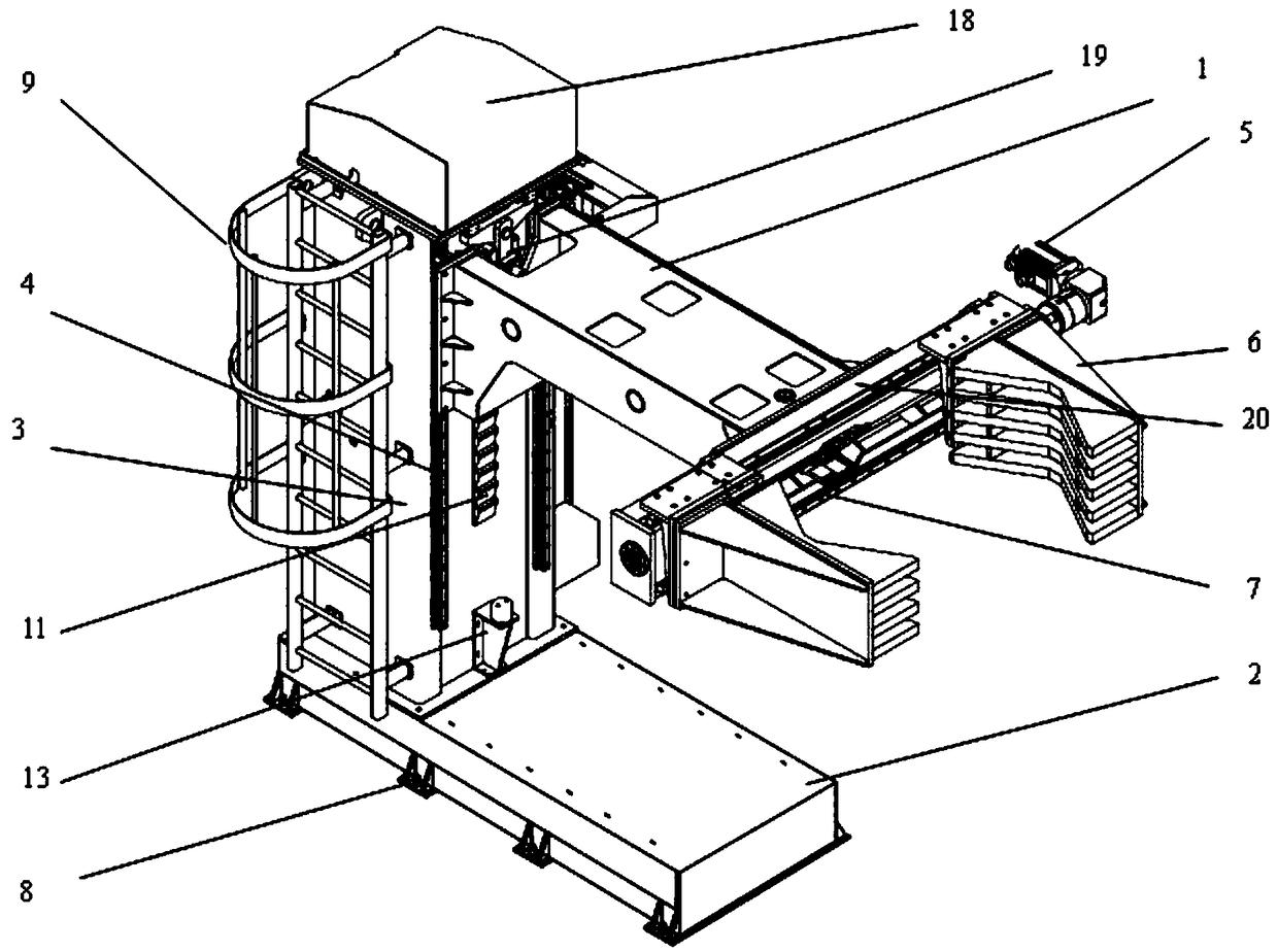
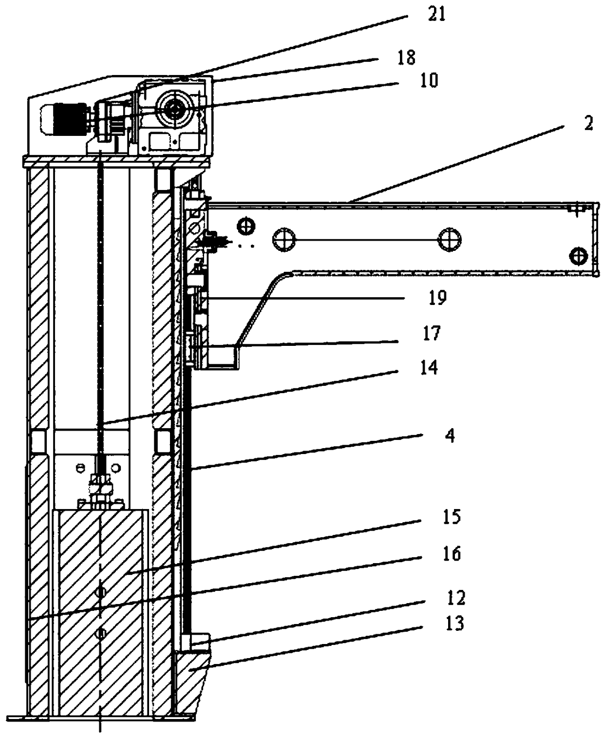
[0014] like figure 1 , figure 2 As shown, the pipeline clamping device of the vertical welding station of the present invention includes a cantilever 1, a base 2 and a column 3; A top cover 18 is provided on the top, and a first motor 10 is installed on the top of the column 3 inside the top cover 18. The first motor 10 controls the cantilever 1 to move up and down on the linear guide rail 4 through a chain, and the column 3 is installed on the outside of the linear guide rail wall. There is a locking rack 11, which cooperates with the locking device 19 installed on the cantilever to prevent the cantilever from sliding down when the cantilever is stationary; the bottom of the column 3 is provided with a linear guide rail 4 and the outside of the wall surface is provided with an up and down sliding limit device 12 to prevent the cantilever from slidi...


PUM


Abstract

The invention provides a pipeline clamping device for a vertical welding table. A column is perpendicular to a base, and one outside wall of the column is provided with a linear guide rail and a locking rack; a top cover of the top of the column is internally provided with a first motor, and the bottom of the column is provided with a sliding limit device used for preventing a cantilever from derailing; the outside wall, adjacent to the side of the linear guide rail, of the column is provided with an escalator, and the outside wall, opposite to the side of the linear guide rail, of the columnis provided with an electric control system; the cantilever is controlled by the first motor through a chain to do linear guide motion, and the locking rack is matched with a cantilever locking device, and used for preventing the cantilever from sliding down; one end of the cantilever is connected to the linear guide rail through a sliding component, while the other end of the cantilever is provided with a clamping component; clamping heads are controlled by a second motor of the clamping component through a lead screw to slide on clamping guide rails for clamping a pipeline; the base is fixedto ground by anchor bolts; the pipeline can be clamped in the pipeline welding process effectively and safely, and the welding deformation is avoided; and the pipeline clamping device has the effectsof high stability and reliability, and is flexible.

Description

technical field [0001] The invention relates to a pipeline clamping device of a vertical welding platform. Background technique [0002] The J-shaped pipe-laying method is currently proven to be the most suitable method for laying submarine pipelines in deep water and ultra-deep water. Because the pipeline enters the water at a nearly vertical angle, the overall shape of the pipeline is J-shaped, so it is named. Since the 1990s, the J-lay method has developed rapidly and has become widely used, and sometimes the only method available when deep sea areas are involved. The appearance of the J-type pipe-laying ship has broken the limitation of water depth on the laying of submarine pipelines, making it possible to explore and develop oil and gas in deep water above 3000m. The J-type pipe laying method is essentially one of the tension pipe laying methods. For different water depths and pipe diameters, during the laying process, the stress state of the pipeline can be improved ...

Claims


Application Information

Patent Timeline
Patent Type & Authority Applications(China)
IPC IPC(8): B23K37/047
CPCB23K37/047
Inventor 栾陈杰孙有辉曹军刘永贞马丽王伟许可望任胜汉信萍
Owner OFFSHORE OIL ENG
Why Eureka
Try Eureka