
Self-irrigating environmentally-friendly flower pot

A kind of flower pot, environmental protection technology, applied in the direction of automatic watering device, container cultivation, gardening, etc., can solve the problem of death of flowers and plants, achieve the effect of avoiding plant withering, strong practicability, and simple structure

Inactive Publication Date: 2018-12-21
刘桂明
View PDF6 Cites 3 Cited by
  • Summary
  • Abstract
  • Description
  • Claims
  • Application Information

AI Technical Summary

Problems solved by technology

[0002] Flowerpot, a kind of vessel used for planting flowers, is in the shape of a rounded platform or a chamfered platform with a large mouth and a small bottom. People use flowerpots to plant flowers and plants, which can improve indoor air quality and promote people's physical and mental health. Under normal circumstances, it can relieve people's fatigue intensity, but some people will forget to water the flowers and plants regularly, which will lead to the death of the flowers and plants

Method used


Image

  • Self-irrigating environmentally-friendly flower pot
  • Self-irrigating environmentally-friendly flower pot
  • Self-irrigating environmentally-friendly flower pot

Examples


Embodiment 1

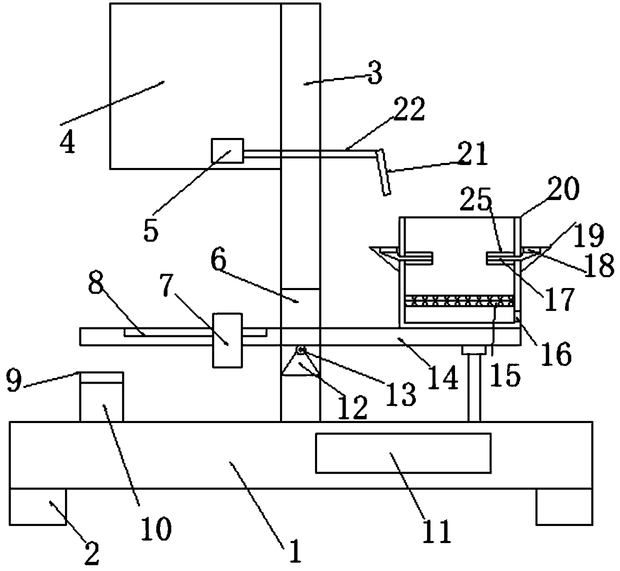
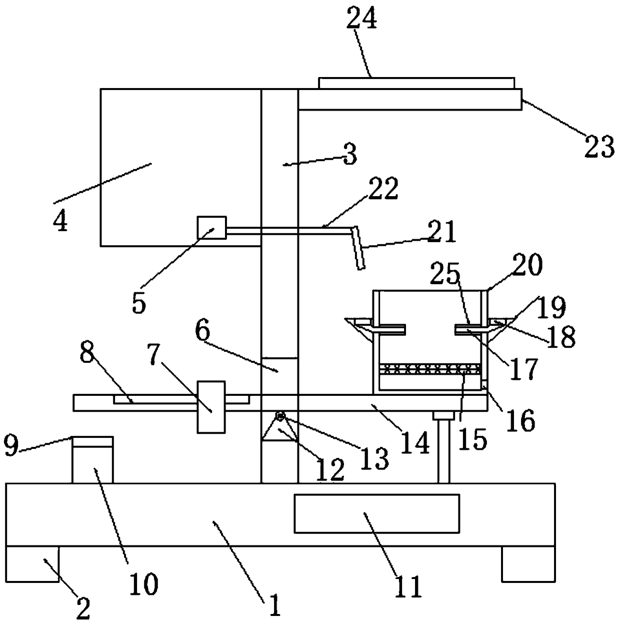
[0020] see Figure 1~3 , in an embodiment of the present invention, a self-irrigating environment-friendly flower pot includes a base 1, and support blocks 2 are symmetrically arranged on both sides of the lower end of the base 1, and a support plate 3 is vertically fixed at the middle position of the upper end of the base 1 to support the The plate 3 is provided with a perforation 6, the bottom of the perforation 6 is provided with a triangular fulcrum block 12, and the upper end of the triangular fulcrum block 12 is provided with a lever plate 14. 14, the upper right side is provided with a planting pot 20, the planting pot 20 is provided with a support grid 15, the planting pot 20 on the lower right side of the support grid 15 is provided with a water leakage hole 16, and the outside of the planting pot 20 is provided with a water collection ring plate 19, the upper end surface of the water collecting ring plate 19 is provided with a water collecting tank 18, and the inner ...

Embodiment 2

[0023] The difference from Embodiment 1 is: the upper right end of the support plate 3 is provided with a side plate 23, the upper end of the side plate 23 is equipped with a solar power generation panel 24, the solar power generation panel 24 is electrically connected to the battery 11, and the photovoltaic power generation 11 charging, so as to play the role of energy saving.


PUM


Abstract

The invention discloses a self-irrigating environmentally-friendly flower pot. The flower pot comprises a base, a supporting plate is vertically fixed to the middle of the upper end of the base, a through hole is formed in the supporting plate, a triangular pivot block is arranged at the bottom of the through hole, a leverage plate is arranged at the upper end of the triangular pivot block, the leverage plate is rotatably connected with the triangular pivot point through a rotary shaft, a planting pot is arranged on the upper right side of the leverage plate, a supporting net grid is arrangedin the planting pot, a draining hole is formed in the planting pot which is located on the lower right side of the supporting net grid, a water collecting annular plate is arranged on the outer side of the planting pot, a water collecting groove is formed in the upper end face of the water collecting annular plate, a plurality of guiding tubes are arranged on the part of the inner wall of the planting pot where the water collecting annular plate is located, and a water guiding passage is arranged in the guiding pipe. The flower pot has the advantages of simple and reasonable structure, a self-irrigation mechanism is provided, when plants are short of water, the left end of the leverage plate is in contact with a touch time delay switch, a liquid pump waters the water collecting groove, a water source is provided for the planting pot, the problem that the plants are withered due to late irrigation is prevented, and the practicability is high.

Description

technical field [0001] The invention relates to the technical field of environmental protection equipment, in particular to a self-irrigating environmental protection flower pot. Background technique [0002] Flowerpot, a kind of vessel used for planting flowers, is in the shape of a rounded platform or a chamfered platform with a large mouth and a small bottom. People use flowerpots to plant flowers and plants, which can improve indoor air quality and promote people's physical and mental health. Under normal circumstances, it can relieve people's fatigue intensity, but some people will forget to water the flowers and plants regularly, which will lead to the death of the flowers and plants. [0003] Really provide a kind of self watering flower pot to above-mentioned problem now. Contents of the invention [0004] The purpose of the present invention is to provide a self-irrigating environment-friendly flower pot to solve the problems raised in the above-mentioned backgro...

Claims


Application Information

Patent Timeline
Patent Type & Authority Applications(China)
IPC IPC(8): A01G9/02A01G27/02A01G27/00
CPCA01G9/02A01G27/003A01G27/02
Inventor 刘桂明
Owner 刘桂明
Learn More