
An image filtering method, storage medium and terminal equipment

An image filtering and input image technology, applied in the field of image processing, can solve the problems of algorithm halo, high computational complexity, and depicting image content, etc.

Active Publication Date: 2022-05-17
SHENZHEN UNIV
View PDF8 Cites 0 Cited by
  • Summary
  • Abstract
  • Description
  • Claims
  • Application Information

AI Technical Summary

Problems solved by technology

However, the computational complexity of this algorithm is very high, and the content scale of natural images is usually arbitrary, so it is difficult to accurately describe the scale of image content with a cross
In summary, there are many improved algorithms for guided filtering, but the existing algorithms still cannot solve the problem of halo phenomenon near the border of the image.

Method used


Image

  • An image filtering method, storage medium and terminal equipment
  • An image filtering method, storage medium and terminal equipment
  • An image filtering method, storage medium and terminal equipment

Examples


Embodiment 1

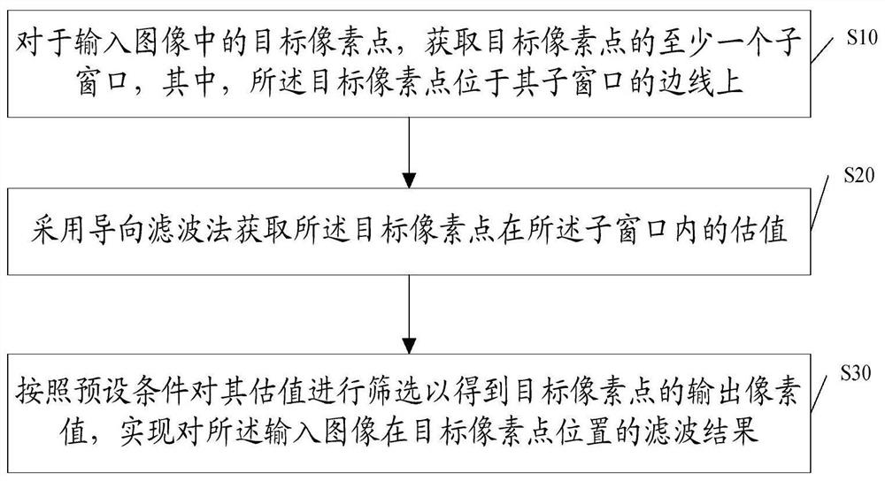
[0064] This embodiment provides an image filtering method, such as figure 1 As shown, the method includes:

[0065] S10. For a target pixel in the input image, acquire at least one sub-window of the target pixel, wherein the target pixel is located on a sideline of the sub-window.

[0066] Specifically, the input image is an image to be processed, which may be an image captured by a camera, or an image sent by an external terminal. Each target pixel point in the input image refers to each pixel point included in the input image. It is assumed here that the number of pixels of the input image is M*N, that is, the number of rows of the pixel matrix of the input image is M, and the number of columns is N. For the target pixel in the input image, its position in the pixel matrix of M*N is used as the coordinate position of the target pixel, and is recorded as (i, j), where i is the target pixel in The row number of the input image pixel matrix, j is the column number of the tar...

Embodiment 2

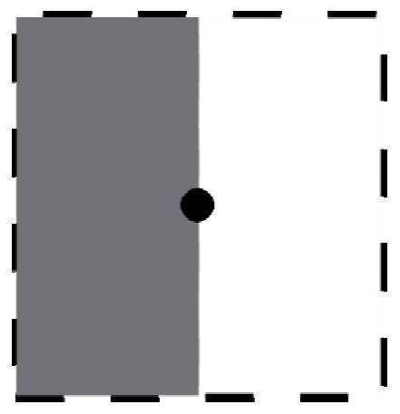
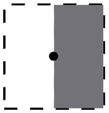
[0135] In the input image, there are few borders with an angle of 45 degrees, and when there are only horizontal or vertical borders, four sub-windows, left sub-window, right sub-window, upper sub-window and lower sub-window, can be obtained through the description of Embodiment 1, and the output The formula for calculating the pixel value is as follows:

[0136]

[0137]

Embodiment 3

[0139] On the basis of Embodiment 2, each sub-window also contains three scales, respectively (r, r+2, r-2), correspondingly, each sub-window will calculate three scales (r, r+2, r -2) Valuation. Here, taking the left sub-window as an example, the target pixel estimates of the three scales are expressed as:

[0140]

[0141] Then for 4 sub-windows, 3 scales for each sub-window, a total of 12 estimates are obtained. Finally, the value of the corresponding pixel of the output image is taken as the value of the corresponding pixel of the output image among the 12 evaluations with the smallest distance from the target pixel of the input image.


PUM


Abstract

The invention discloses an image filtering method, a storage medium and a terminal device. The method includes: for a target pixel in an input image, obtaining at least one sub-window of the target pixel, wherein the target pixel is located in the sub-window on the edge; using guided filtering method to obtain the estimated value of the target pixel in each sub-window; according to the preset conditions, each estimated value is screened to obtain the output value of the target pixel, and the input image is realized filtering. In the present invention, by selecting a sub-window that contains the target pixel and that the target pixel is located on its sideline, the estimation of the target pixel in the sub-window is calculated by a guided filtering algorithm, and the estimation that satisfies the preset condition is used as the output pixel value to solve the problem of using The boundary blur problem exists when the guided filtering algorithm performs filtering.

Description

technical field [0001] The present invention relates to the technical field of image processing, in particular to an image filtering method, storage medium and terminal equipment. Background technique [0002] In the field of image processing technology, due to the influence of the shooting environment, camera, etc., the captured image often has noise, which affects the image command, so it is often necessary to filter the image to remove the noise in the image. In order to remove the noise in the image, the currently commonly used filtering algorithm is the guided filtering method. The output image of the guided filtering is similar to the input image as a whole but similar in structure to the guided image, although the guided filtering algorithm can better maintain the image boundary. , however, halos appear near the borders of the image. [0003] In order to solve the problem of halo phenomenon in the vicinity of the boundary of the image in the guided filtering algorith...

Claims


Application Information

Patent Timeline
Patent Type & Authority Patents(China)
IPC IPC(8): G06T5/00
CPCG06T2207/20024G06T5/94G06T5/70
Inventor 殷慧龚元浩邱国平
Owner SHENZHEN UNIV
Learn More