
Test device and test method for I-II composite crack fatigue propagation rate

A crack fatigue propagation, I-II technology, applied in the field of the I-II composite crack fatigue growth rate test device, can solve the problem of insufficient test accuracy and reliability, and inability to easily achieve sample alignment

Active Publication Date: 2018-12-18
SOUTHWEST JIAOTONG UNIV
View PDF4 Cites 14 Cited by
  • Summary
  • Abstract
  • Description
  • Claims
  • Application Information

AI Technical Summary

Problems solved by technology

[0004] The present invention aims to provide a kind of I-II compound type crack fatigue growth rate test device, to solve the problem that the crack fatigue growth rate test device in the prior art cannot conveniently realize the centering of the sample, and the test accuracy and reliability are insufficient

Method used


Image

  • Test device and test method for I-II composite crack fatigue propagation rate
  • Test device and test method for I-II composite crack fatigue propagation rate
  • Test device and test method for I-II composite crack fatigue propagation rate

Examples


Embodiment

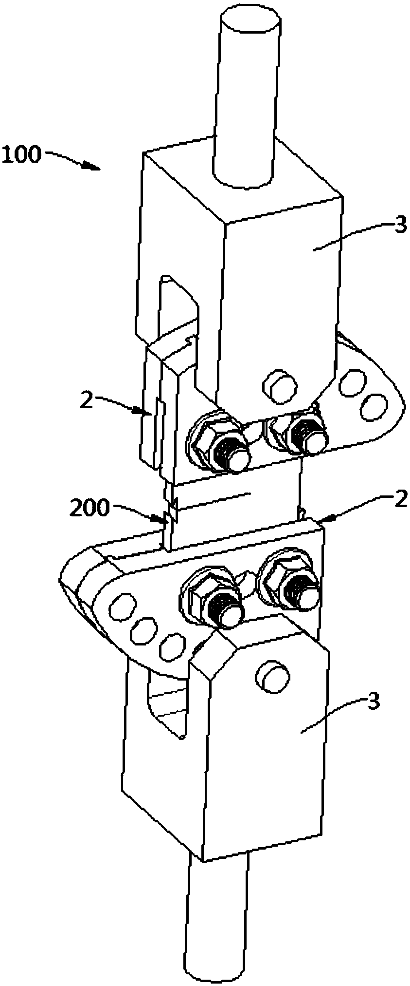
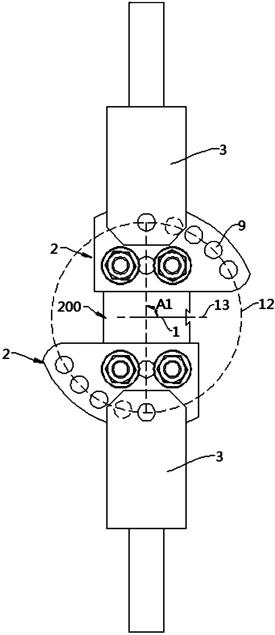
[0076] figure 1 Shows the I-II composite crack fatigue growth rate test device 100 and the connected sample 200 in the embodiment of the present invention; figure 2 Yes figure 1 The first perspective view; image 3 Yes figure 1 Second perspective view; Figure 4 for figure 2 Section view of Figure 5 for figure 1 Exploded view.

[0077] Image 6 A view under one embodiment of the sample 200 is shown. See Image 6 In this embodiment, the sample 200 is generally a plate-shaped structure, and a strip-shaped predetermined crack 1 extending inward from one side of the sample 200 is provided between its two ends. . The test device 100 can be used to apply an external tensile force perpendicular to the crack or obliquely intersecting with the crack to the sample 200, optionally a reciprocating external tensile force repeated multiple times, through the crack under the action of the tensile test load The data obtained by the measurement and processing of the expansion of the sample ca...

Embodiment approach

[0088] The following specifically introduces an embodiment of the I-II compound crack fatigue growth rate test device 100 test: Step (1): I-II compound crack fatigue growth test

[0089] After clamping a CTS sample 200 with the aforementioned I-II compound crack fatigue growth rate test method, start to load the test load with the size set to P and the number of cycles to N, and record the preset crack mouth under this load Opening displacement V, collect load P, crack mouth opening displacement V and cycle number N during the test, and save (P, V, N) experimental data.

[0090] According to the test load P-crack mouth opening displacement V curve, the flexibility C is obtained *

[0091]

[0092] Where C * Is the flexibility, P is the test load, V is the opening displacement of the 200 crack mouth of the CTS sample, C * It can be obtained by regression of the P-V test data obtained from the test, and the number of loading cycles N is collected during the test.

[0093] Step (2): I-II...


PUM


Abstract

The invention relates to the technical field of mechanical experimental devices and testing methods, aims to solve the problems that the test device for crack fatigue propagation rate in the prior artcannot conveniently realize the alignment of samples, and the test precision and reliability are insufficient, and provides a test device and a test method for I-II composite crack fatigue propagation rate. The test device for I-II composite crack fatigue propagation rate comprises two clamps for respectively clamping both ends of a sample, wherein each clamp comprises two clamp plates having opposite surfaces and a locking structure connecting the two clamp plates; the locking structure is configured to lock the two clamp plates to clamp the sample or to loosen the two clamp plates to release the sample; and the clamps are configured to be clamped on the corresponding end of the sample in the form of making the corresponding end of the sample clamped between the two clamp plates and connected onto the locking structure. The test device and test method for I-II composite crack fatigue propagation rate provided by the invention have the beneficial effect of conveniently ensuring that the clamped sample is in the correct, for example, centered posture, thereby ensuring the accuracy and reliability of the implementation.

Description

Technical field [0001] The invention relates to the field of mechanics experimental device technology and testing methods, and in particular to an I-II compound crack fatigue growth rate testing device and testing method. Background technique [0002] In actual structural engineering (such as pressure vessels, pipe shafts, blades) cracks, holes and other defects are often in a complex stress state, and the research on fatigue growth of I-II compound cracks has a more realistic engineering background. [0003] In the test method and device in the prior art, the loading slot of the sample embedding fixture is connected by a pin to realize loading. Due to the gap between the sample and the wall of the loading slot, it is difficult for the loading load to pass through the symmetry plane of the sample thickness, and the two sides of the sample Unsymmetrical crack growth results in large errors in the measurement of crack growth length, and there are problems such as inconvenient impleme...

Claims


Application Information

Patent Timeline
IPC IPC(8): G01N3/32
CPCG01N3/32G01N2203/0005G01N2203/0066G01N2203/0073
Inventor 祁爽蔡力勋包陈刘晓坤
Owner SOUTHWEST JIAOTONG UNIV
Learn More