Air outlet mounting structure for fresh air system

A technology of installation structure and fresh air system, applied in air conditioning system, ventilation layout, space heating and ventilation, etc., can solve the problems of troublesome installation, inability to achieve complete sealing, and high installation requirements, and achieve simple structure, improved aesthetics, free of charge. The effect of the disassembly process

Inactive Publication Date: 2018-12-18
HANGZHOU FILTECH INTELLIGENT CO LTD
View PDF10 Cites 0 Cited by
  • Summary
  • Abstract
  • Description
  • Claims
  • Application Information

AI Technical Summary

Problems solved by technology

However, in order to achieve the sealing between indoor and outdoor, the above-mentioned structure needs to install sealing rubber strips on both sides of the first baffle, which is not only troublesome to install, but also requires high installation requirements, and cannot achieve a complete sealing effect.

Method used


Image

  • Air outlet mounting structure for fresh air system
  • Air outlet mounting structure for fresh air system
  • Air outlet mounting structure for fresh air system

Examples


Embodiment 1

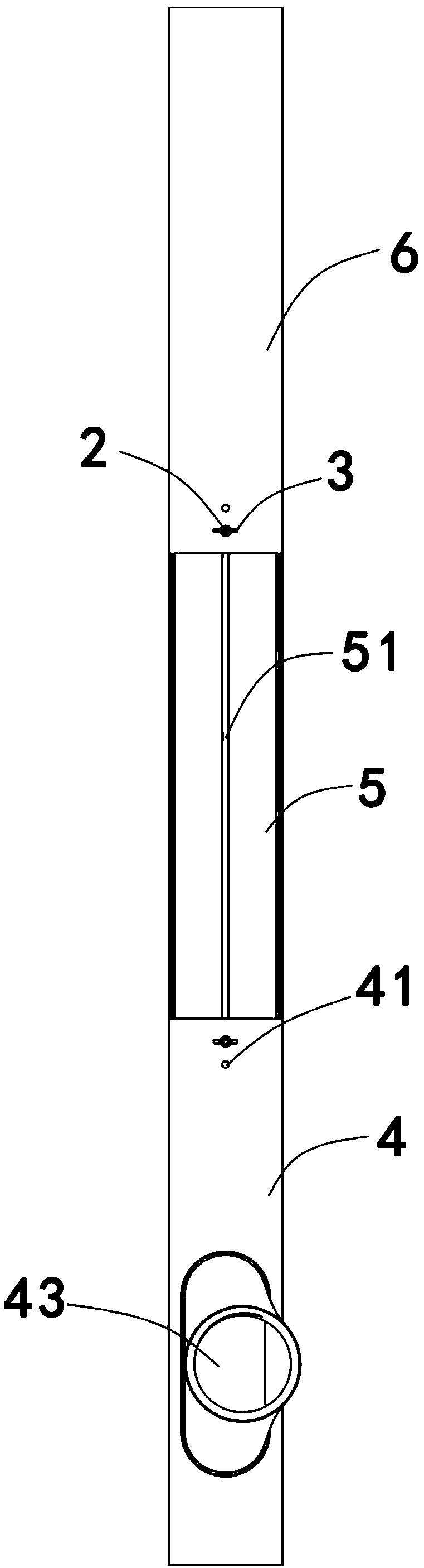
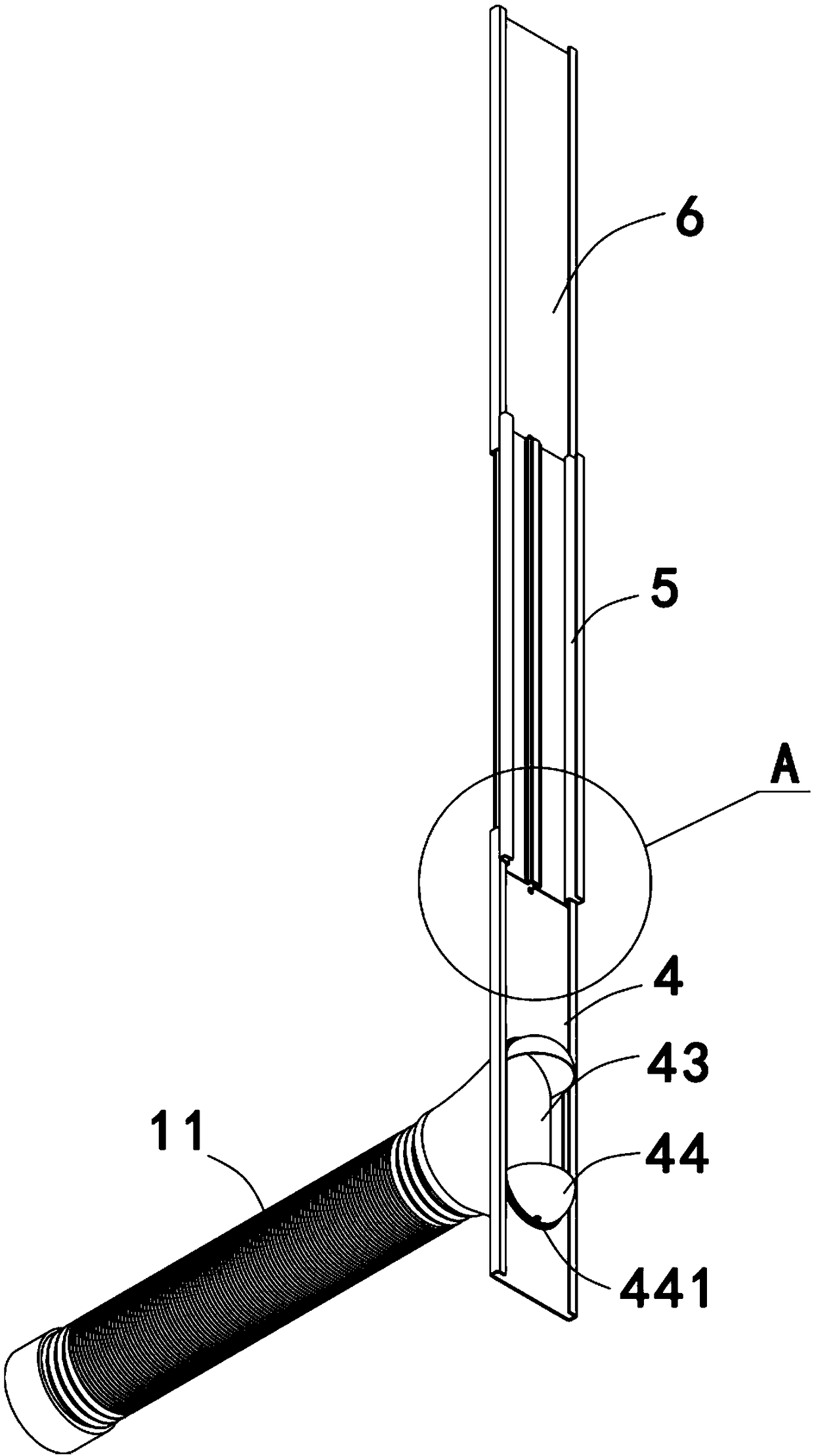
[0033] Such as Figure 1-9 As shown, an air outlet installation structure of the fresh air system is used for the air outlet of the fresh air system. The installation structure includes a first baffle plate 4, a second baffle plate 5 slidingly connected to the upper part of the first baffle plate 4, and a second baffle plate 5 for connecting the first baffle plate 4. The connecting piece 2 and the fastening piece 3 of the baffle 4 and the second baffle 5 . The first baffle plate 4 is a strip-shaped flat plate structure, and its two sides along the length direction are bent inwardly to form a card slot 42 with an opening facing inward. The cross section of the card slot 42 is U-shaped. Part of it is inserted into the slot 42. Specifically, the two sides of the second baffle plate 5 are bent to form a convex portion that is adapted to the internal shape and size of the slot 42, and the free end of the convex portion continues along the edge of the slot 42. The outer wall is ben...

Embodiment 2

[0039] Such as Figure 10-15 As shown, an air outlet installation structure of a fresh air system, the difference between this embodiment and Embodiment 1 is that the positions of the first baffle and the second baffle are interchanged, and the two sides of the second baffle 4 along the length direction The edge is bent inwardly to form a slot 42 with an opening facing inward. The cross section of the slot 42 is U-shaped, and the lower part of the first baffle 5 is inserted into the slot 42. Specifically, both sides of the first baffle 5 The edge is bent to form a convex portion adapted to the internal shape and size of the slot 42, and the free end of the convex portion continues to bend outwards along the outer wall of the slot 42 to form an extension section 53. When the extension section 53 and the outside of the slot 42 After the wall is flush, its tail end continues to bend along the direction perpendicular to the front of the first baffle plate 5 to form a thickened por...


PUM


Abstract

The invention discloses an air outlet mounting structure for a fresh air system. The air outlet mounting structure is used for mounting an air outlet of the fresh air system on a window. The air outlet mounting structure comprises a connecting piece, a fastening piece, a first baffle, a second baffle and a third baffle. The second baffle and the first baffle are slidably matched in the height direction. The two side edges of the first baffle, the second baffle and the third baffle are flush. A mounting hole is formed in the first baffle, and a linear groove extending in the height direction ofthe second baffle is formed in the position, corresponding to the mounting hole, on the second baffle. A limiting cavity is defined by the side, away from the first baffle, of the linear groove, theend of the connecting piece is clamped into the limiting cavity, and the other end of the connecting piece penetrates through the mounting hole and then is connected with the fastening piece. The airoutlet mounting structure is simple and reasonable in design, can be adjusted at random in height to adapt to the height of the window, and adapt to a frame of the opened window in width and thickness, sealing connection between a connecting structure and the window can be achieved without sealing rubber strips, adaptability is high, and adjusting is convenient.

Description

technical field [0001] The invention belongs to the field of installation of air purification systems, and in particular relates to an installation structure of an air outlet of a fresh air system. Background technique [0002] With the continuous improvement of people's requirements for quality of life, air purifiers are widely used. In order to install air purifiers on buildings that have completed decoration or are not suitable for installing more complex structures, more and more windows are installed on the market. The form of the fresh air system. Chinese patent CN 106594888 discloses a fresh air purifier and its installation method, which can adapt to the height of the window by setting the two telescopic structures of the fixed part and the movable part through the first baffle, so as to solve the problem of installing the fresh air purifier on windows of different heights. However, in order to achieve the sealing between the indoor and the outdoor, the above-mentio...

Claims


Application Information

Patent Timeline
IPC IPC(8): F24F13/02E06B7/02
CPCE06B7/02F24F13/0227F24F13/0254F24F2221/20F24F2221/26
Inventor 沈亚斌
Owner HANGZHOU FILTECH INTELLIGENT CO LTD
Why Eureka
Try Eureka