
A spring support hanger

A technology for supporting hangers and hanging plates, which is applied in the field of supporting and hanging frames, can solve the problems of different spring deformation lengths, uneven heights, and inability to adjust the height of installation clips, so as to reduce impact noise and improve consistency.

Active Publication Date: 2020-06-02
镇江笑宁能源科技有限公司
View PDF1 Cites 0 Cited by
  • Summary
  • Abstract
  • Description
  • Claims
  • Application Information

AI Technical Summary

Problems solved by technology

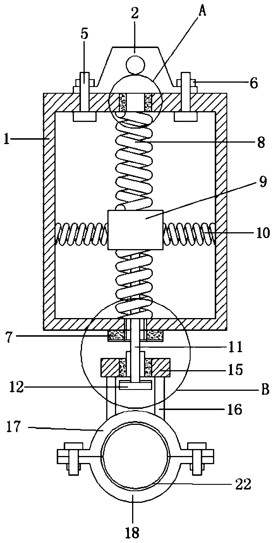
[0004] In the practical application of the spring support hanger, considering the limitation of space and the requirement of fixing the actual height, etc., it is required that the spring support hanger can not only have a good shock absorption effect, but also be able to adjust the installation height of the pipeline within a certain range. However, the device cannot adjust the height of the installation clip, and the height of the pipe installation cannot be adjusted. Moreover, due to the different weights of the loaded pipes, the deformation length of the spring is different, and the installation heights of different pipes are uneven, and when adjusting the direction of the pipe installation clip , due to space constraints, it is very inconvenient to install and disassemble the fasteners that adjust the direction. Therefore, we propose a spring support hanger

Method used


Image

  • A spring support hanger
  • A spring support hanger
  • A spring support hanger

Examples


Embodiment Construction

[0026] The following will clearly and completely describe the technical solutions in the embodiments of the present invention with reference to the accompanying drawings in the embodiments of the present invention. Obviously, the described embodiments are only some, not all, embodiments of the present invention. Based on the embodiments of the present invention, all other embodiments obtained by persons of ordinary skill in the art without creative efforts fall within the protection scope of the present invention.

[0027] In describing the present invention, it should be understood that the terms "upper", "lower", "front", "rear", "left", "right", "top", "bottom", "inner", " The orientation or positional relationship indicated by "outside", etc. is based on the orientation or positional relationship shown in the drawings, and is only for the convenience of describing the present invention and simplifying the description, rather than indicating or implying that the referred dev...


PUM


Abstract

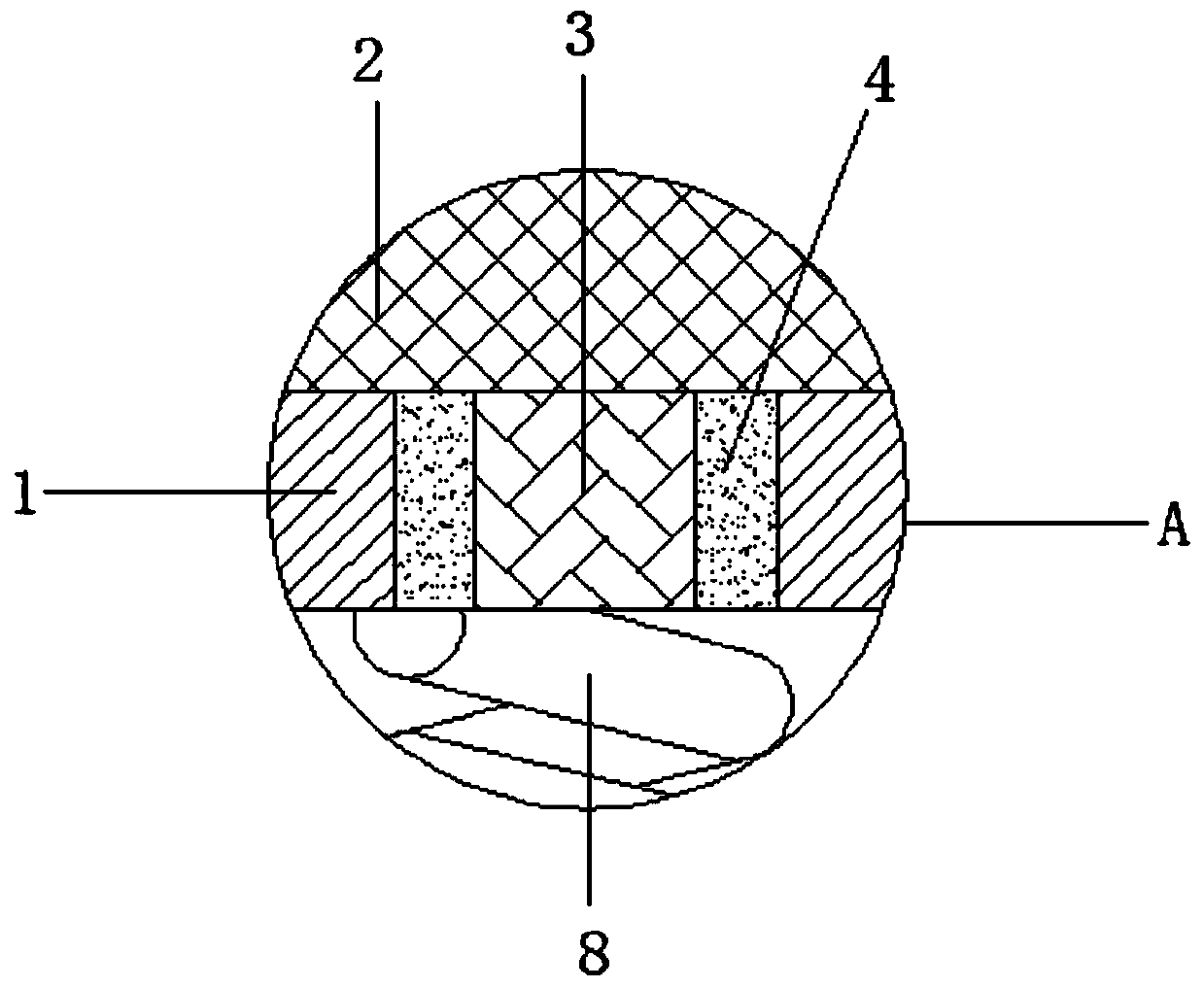
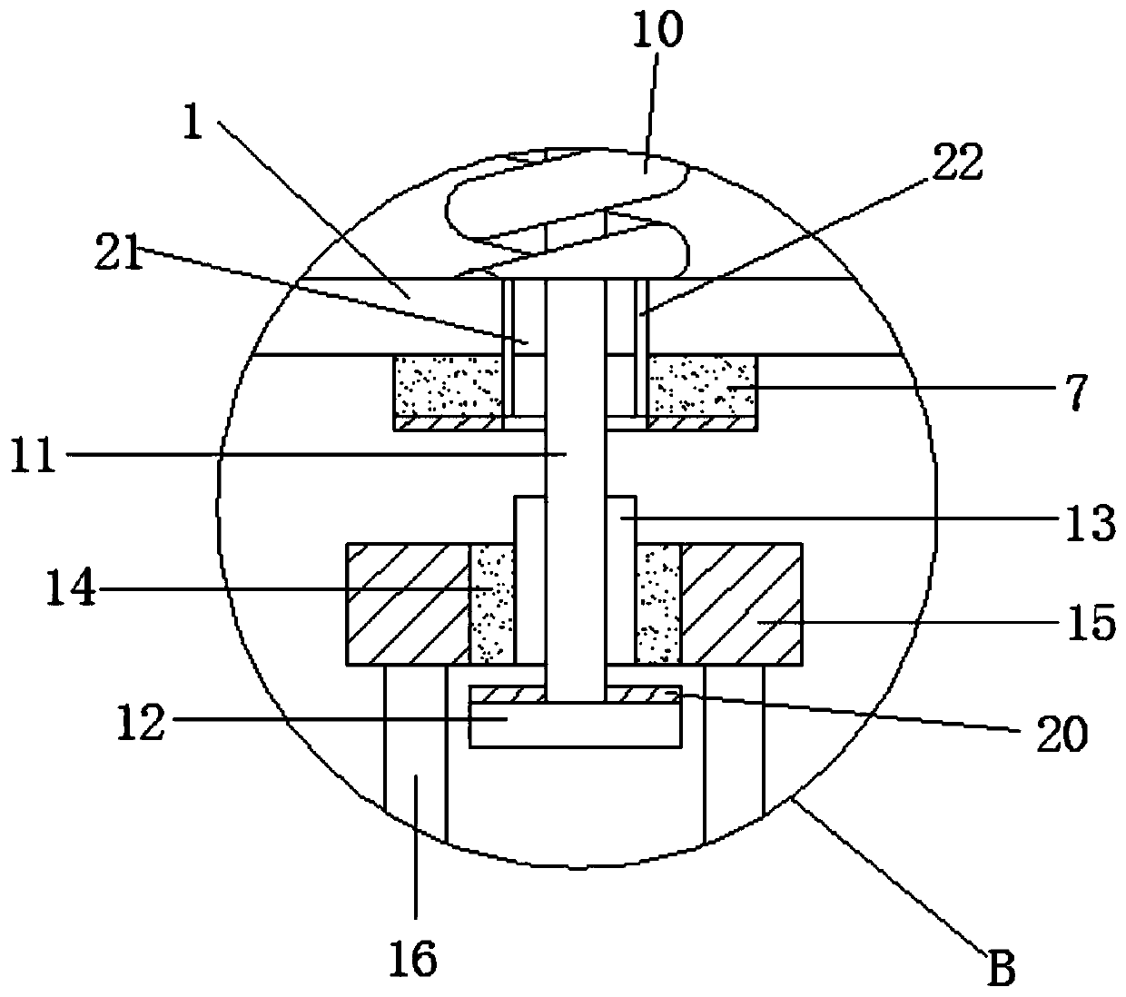
The invention relates to the technical field of hangers, in particular to a spring hanger which comprises a shell. A hanger plate is arranged on the top part of the shell; a rotary shaft and a first bearing are fixedly connected to the bottom part of the hanger plate; the shell is connected with the hanger plate through a T-shaped bolt; an upper limiting block is arranged on the bottom part of theshell; a connecting block is arranged in an inner cavity of the shell; longitudinal springs and horizontal springs are arranged on the periphery of the connecting block; a screw rod is arranged on the bottom part of the connecting block; a lower limiting block is arranged on the bottom part of the screw rod; the screw rod is connected with an adjusting nut in a sleeving way; the adjusting nut isconnected with a second bearing in a sleeving way; the second bearing is connected with a support plate in a sleeving way; a connecting rod is arranged on the bottom part of the support plate; an upper pipeline installation clip is arranged on the bottom part of the connecting rod; and a lower pipeline installation clip is connected to the bottom part of the upper pipeline installation clip. According to the spring hanger provided by the invention, the heights of the pipeline installation clips can be adjusted within the adjusting range, so that the requirement for actual application of the pipeline heights in reality is met, the pipeline installation direction is adjusted simply and conveniently, and the favorable shock absorption and noise reduction effects are achieved.

Description

technical field [0001] The invention relates to the technical field of support and hangers, in particular to a spring support and hanger. Background technique [0002] The spring support hanger is within the specified load displacement range, and the load moment and spring moment are always balanced. It is a kind of load-bearing support and hanger. It is used in places where the pipeline displacement is not large. It plays an important role in the thrust or moment it bears and is widely used in pipeline construction. [0003] The application number is 201721260193.X, and the patent name is a spring support and hanger, which includes a shell, a hanging plate on the top of the shell, and a spring pressing plate inside the shell. The upper end of the spring pressing plate is connected to a vertical spring, and the top end of the vertical spring is fixed on the On the inner wall of the top of the shell, there is a connecting rod under the spring pressure plate. There are at lea...

Claims


Application Information

Patent Timeline
Patent Type & Authority Patents(China)
IPC IPC(8): F16L3/16F16L3/11F16F15/08
CPCF16F15/046F16F15/08F16L3/1091F16L3/11F16L3/16
Inventor 陈庆
Owner 镇江笑宁能源科技有限公司
Learn More