
Board combination connecting buckle

A combined connection and buckle technology, applied in the direction of thin plate connection, connecting components, mechanical equipment, etc., can solve the problems of inability to support the plate, press the edge, easy installation errors, etc., and achieve the effect of improving the effect and improving the stability.

Active Publication Date: 2018-12-18
淮北创之社信息科技有限公司
View PDF4 Cites 7 Cited by
  • Summary
  • Abstract
  • Description
  • Claims
  • Application Information

AI Technical Summary

Problems solved by technology

[0002] At present, when carrying out furniture installation and combination, it is necessary to drill holes on the boards to facilitate the fixed installation of the connecting components, so that two adjacent boards are fixedly connected. This connection method requires drilling holes on the boards, and There are requirements on the placement position of the board during assembly, and it is easy to install incorrectly. Therefore, there is a connection buckle for clamping the board. The buckle uses two sets of guide grooves perpendicular to each other to clamp the board in the guide groove, and then from the single The side is fixed with a set screw, so that the two plates are connected and fixed, but because the fixed point is compressed by a single set screw, when rotating, the screw and the push plate fit together, and the plate is squeezed and fixed by the push plate, and the spiral rotation will The push plate is deflected, so that there is an angle between the push plate and the plate, which cannot form an effective support for the plate, and when the push plate is deflected to the edge of the plate, the edge of the plate will appear under pressure, causing fixing problems , and due to the deflection of the push plate, there is a margin of relative movement between the plates, making the fixed plates unstable

Method used


Image

  • Board combination connecting buckle
  • Board combination connecting buckle
  • Board combination connecting buckle

Examples


Embodiment 1

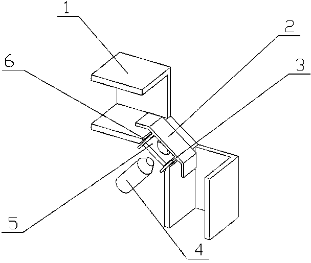
[0037] Such as figure 1 As shown: the joint buckle of the board combination of the present invention is realized in this way, including the corner mounting plate (5), the locking part and the pressure plate (1), and the corner mounting plate (5) is made of metal plates twice consecutively It is bent and forms three bending parts, the locking part is placed on the bending part in the middle of the corner mounting plate (5), and the two pressure plates (1) are respectively placed on the outside of the corner mounting plate (5) on the two bends of the

[0038] The extension lines of the center lines of the two outer bending parts of the corner mounting plate (5) are perpendicular to each other;

[0039] The two outer bending parts of the corner mounting plate (5) have the same length and are twice the length of the middle bending part, which can increase the supporting surface for the plate, and push the push in with less screwing. The plate (2) is pushed to the plate for clamp...

Embodiment 2

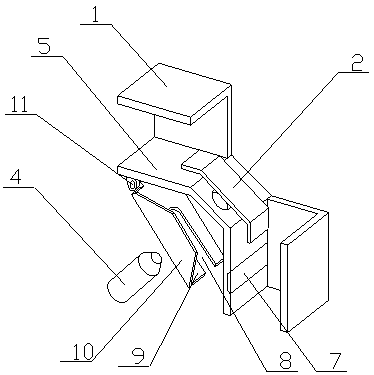
[0056] Such as figure 1As shown, the bottom of the corner mounting plate (5) is equipped with a protective part, and the protective part is composed of an opening slot (8), a lower baffle (9), a side baffle (10) and a hinged frame (11). One end of the lower baffle (9) is hinged to the bottom of one end of the corner mounting plate (5) through the hinged frame (11). The lower baffle (9) is provided with an opening slot (8), and the opening is located 9) At the other end, two side baffles (10) are respectively placed on both sides of the lower baffle (9). ) and the lower baffle (9) are made of metal materials;

[0057] A magnetic strip (7) is placed on the corner mounting plate (5) and is close to the other end of the corner mounting plate (5);

[0058] After the wooden boards are compressed and fixedly connected by the locking part, the lower baffle (9) is rotated, and the lower baffle (9) drives the side baffles (10) on both sides to move, so that the edges of the two side b...

Embodiment 3

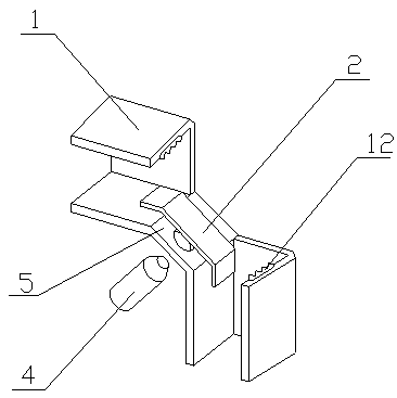
[0060] Such as image 3 As shown: the pressure plate (1) has an anti-skid tooth plate (12) inside, and corresponds to the corresponding part of the corner mounting plate (5);

[0061] One side of the anti-slip tooth plate (12) is equipped with multiple groups of teeth at equal distances, each group of teeth is composed of at least five teeth, and there is a gap between two adjacent teeth in the same group, and the surface of the teeth is provided with Rubber mat.

[0062] After the wooden boards are compressed and connected by the locking part, the anti-slip tooth plate (12) is attached to the surface of the wooden board, and the friction force between the anti-skid toothed plate (12) and the wooden board is relatively large, and when the wooden board is pressed tightly, it can prevent The wooden board slides in the installation groove to ensure the connection area between the wooden board and the connecting buckle, as well as the load-bearing capacity, and thus better safety...


PUM


Abstract

The invention discloses a board combination connecting buckle. According to the connecting buckle, a push plate is prevented from rotating in the pressing process, and the pressing fixing effect on boards can be improved, connecting and fixing stability of two boards can be effectivley improved, and the buckle is characterized by comprising an angular mounting plate, a locking part and pressing plates, the angular mounting plate is formed through continuous two-time bending of a metal board, three bending parts are formed, the locking part is placed on the bending part in the middle of the angular mounting plate, two pressing plates are arranged on the two bending parts on the outer portion of the angular mounting part, and center line extension lines of two bending parts, close to the outside, of the angular mounting plate are perpendicular.

Description

technical field [0001] The invention relates to a combined connection buckle for plates, which relates to a combined connection buckle for connecting and fixing plates in furniture installation, belongs to the field of furniture processing, and particularly relates to a method for preventing the push plate from rotating during the pressing process, improving the The connection buckle of the pressing and fixing effect on the board. Background technique [0002] At present, when carrying out furniture installation and combination, it is necessary to drill holes on the boards to facilitate the fixed installation of the connecting components, so that two adjacent boards are fixedly connected. This connection method requires drilling holes on the boards, and in There are requirements on the placement position of the board during assembly, and it is easy to install incorrectly. Therefore, there is a connection buckle for clamping the board. The buckle uses two sets of guide groove...

Claims


Application Information

Patent Timeline
IPC IPC(8): F16B5/06F16B5/02
CPCF16B5/02F16B5/0614F16B2005/0678
Inventor 不公告发明人
Owner 淮北创之社信息科技有限公司
Learn More