
Filter and engine assembly

A filter and filter tank technology, which is applied in the installation/connection of lubricant purification devices, lubricating parts, pressure lubricants, etc., can solve the problems of easy oil flow, wear, and lack of oil in moving parts, so as to prevent wear effect

Active Publication Date: 2018-12-18
WEICHAI POWER CO LTD
View PDF6 Cites 2 Cited by
  • Summary
  • Abstract
  • Description
  • Claims
  • Application Information

AI Technical Summary

Problems solved by technology

[0008] One object of the present invention is to provide a filter to solve the problem of the oil filter in the prior art. When the engine is stopped, the oil in the filter tank will flow out of the filter tank, causing the moving parts to be short-lived when the engine is started. Lack of oil, easy to cause wear problems
[0009] Another object of the present invention is to provide an engine assembly to solve the problem that the oil in the filter tank of the oil filter in the prior art is easy to flow out after the engine stops, and it takes time to remove the oil filter after the engine is restarted. The filter canister is filled with oil, during which time it is easy to cause wear problems of moving parts

Method used


Image

  • Filter and engine assembly
  • Filter and engine assembly
  • Filter and engine assembly

Examples


Embodiment Construction

[0036] The technical solutions of the present invention will be further described below in conjunction with the accompanying drawings and through specific implementation methods.

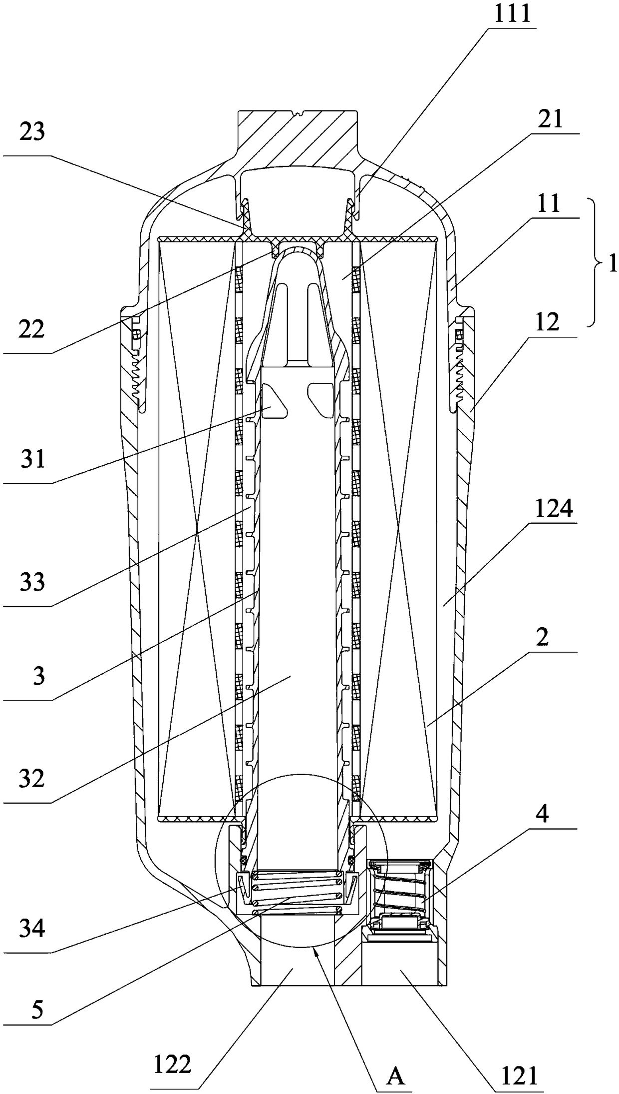
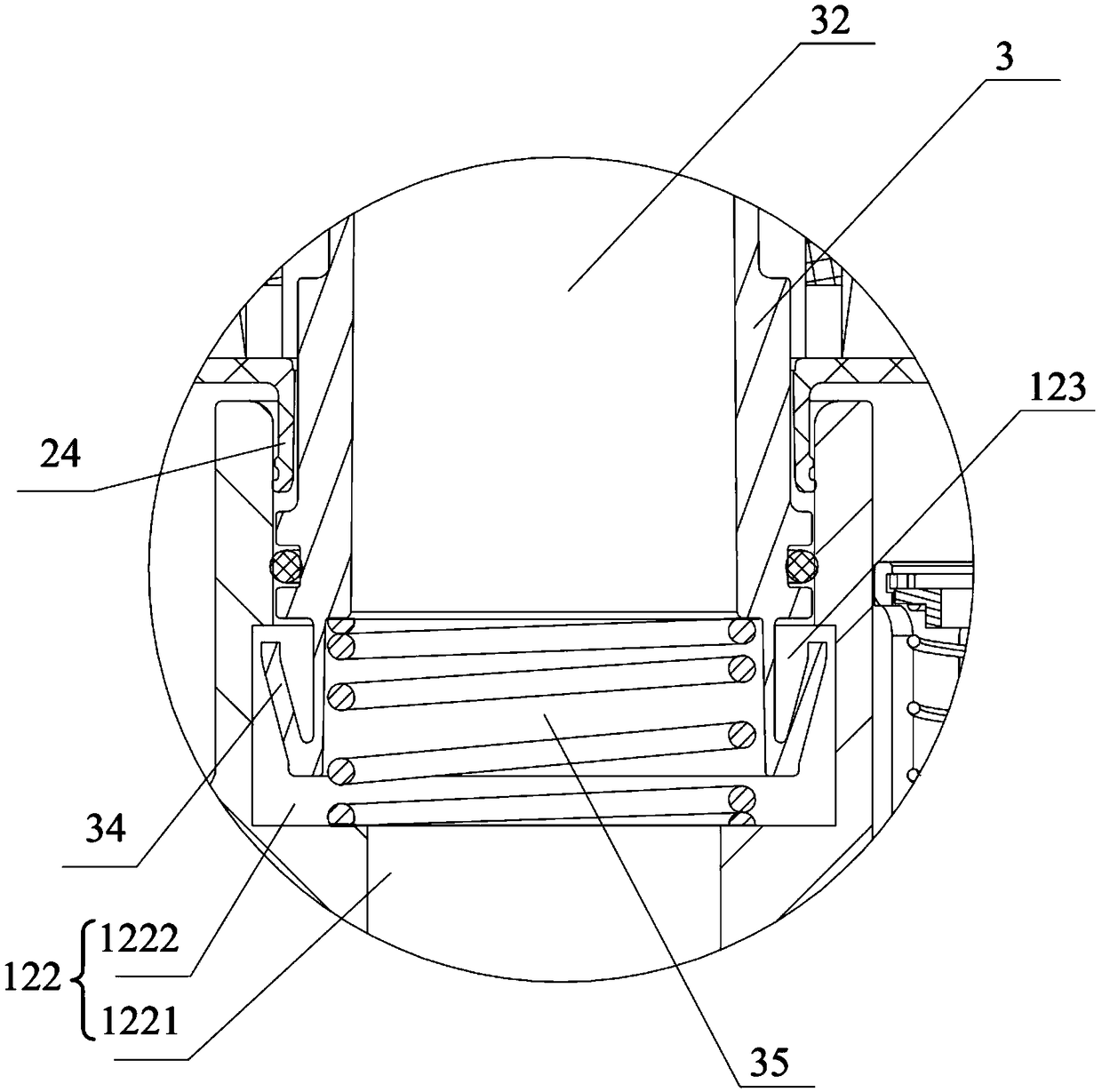
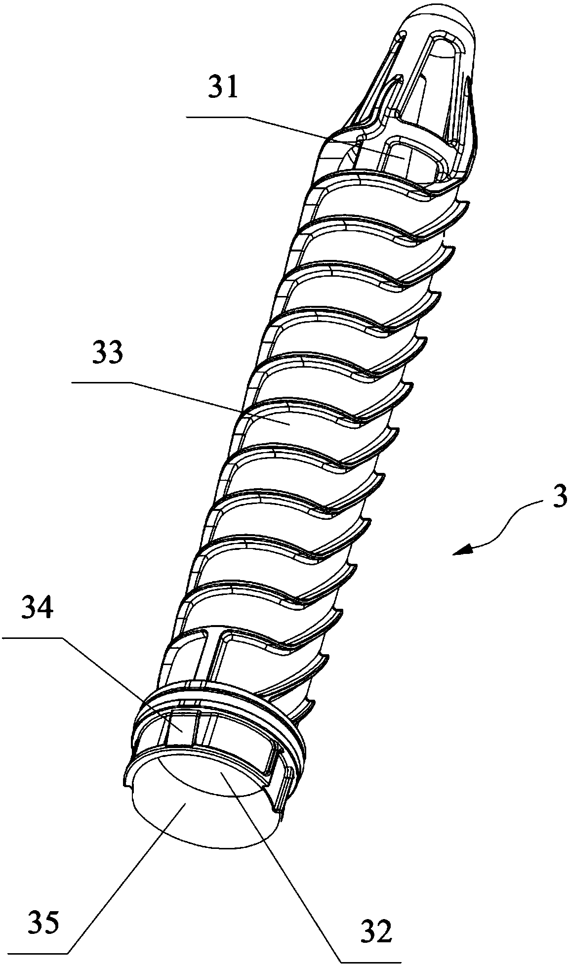
[0037] Such as Figure 1~3 As shown, the present embodiment provides a filter, which includes a filter tank 1, a filter element 2, a middle pipe 3 and a first one-way valve 4, the inside of the filter tank 1 is provided with a filter cavity 124, and the filter tank 1 is provided with an oil inlet 121 and an oil outlet 122 communicating with the filter cavity 124, the oil outlet 122 is connected with the main oil passage, the first check valve 4 is installed at the oil inlet 121, the oil inlet 121 is connected with the oil The pan is communicated with the pipeline, and the engine oil can enter the filter cavity 124 from the oil pan through the first one-way valve 4, so that after the engine stops, the engine oil in the filter cavity 124 will not flow back to the oil pan through the oil inlet 121 mid...


PUM


Abstract

The invention relates to the field of engine assemblies, in particular to a filter. The filter comprises a filter tank, a filter element, a middle pipe and a first one-way valve, wherein a filter cavity is arranged in the filter tank; an oil inlet and an oil outlet communicating with the filter cavity are formed in the filter tank; the filter element is arranged in the filter cavity; an installation hole is formed in the filter element; an oil guiding channel is arranged in the middle pipe; the middle pipe is partially located in the installation hole; one end of the bottom part is in seal connection with the filter tank; a through hole is formed in one end of the top part of the middle pipe; two ends of the through hole communicate with the filter cavity and the oil guiding channel; the oil guiding channel communicates with the oil outlet, so that engine oil in the filter tank can be only discharged from the oil outlet through the through hole in the top part of the middle pipe; the first one-way valve is arranged on the oil inlet; the engine oil can enter the filter cavity through the first one-way valve so as not to backflow to an oil pan after the engine is stopped; and by combining the middle pipe, the engine oil located under the through hole in the filter tank cannot be discharged after the engine is stopped, and the engine oil in the filter tank is quickly fully filledwhen the engine is started again, so that the lubrication of a moving part is ensured.

Description

technical field [0001] The invention relates to the field of engine assembly, in particular to a filter and the engine assembly. Background technique [0002] The main function of the oil filter is to filter out metal and non-metal impurities, colloids and other harmful substances in the oil through the filter element, so as to ensure the cleanliness of the oil in the lubricating parts, reduce wear and prolong the service life of the machine. [0003] However, the existing oil filter has the following problems: [0004] 1) When the engine is stopped, especially for the oil filter whose oil outlet is set under the filter canister, the oil in the filter canister will be empty, and the oil needs to be refilled when restarting. The oil can enter the lubricating oil passage through the oil outlet to lubricate the moving parts, resulting in short-term oil shortage of the moving parts, especially when the engine is frequently started and stopped, which will aggravate the wear of t...

Claims


Application Information

Patent Timeline
Patent Type & Authority Applications(China)
IPC IPC(8): F01M11/03
CPCF01M11/03
Inventor 赵建洲李建文王超崔永张俊龙
Owner WEICHAI POWER CO LTD
Learn More