Multi-purpose mechanical hand clamp

A manipulator and multi-purpose technology, applied in the direction of manipulators, chucks, manufacturing tools, etc., can solve the problems of limited scope of application, easy rebound and shaking of the clamp arm, shaking of objects, etc., and achieve the effect of wide application range

Inactive Publication Date: 2018-12-18
JIANGSU YUBO AUTOMATION EQUIP CO LTD
View PDF5 Cites 6 Cited by
  • Summary
  • Abstract
  • Description
  • Claims
  • Application Information

AI Technical Summary

Problems solved by technology

Existing grippers for manipulators are usually only equipped with clamp arms that can be opened or closed to clamp objects, while some objects have protruding edges on both sides, and the contact area between the edges and the clamp arms is small, resulting in objects being clamped The arm shakes and cannot clamp the object. Therefore, the existing manipulator clamp has a single function and is limited in scope of application.
In addition, the existing manipulator clamps usually change the opening angle of the clamp arm through the telescopic adjustment rod to grasp the object. The clamp arm is directly rigidly connected with the telescopic adjustment rod. During the clamping process, the clamp arm is prone to bounce and shake, thus reducing the The stability of the gripping effect makes the item easy to fall off from the gripper arm

Method used


Image

  • Multi-purpose mechanical hand clamp
  • Multi-purpose mechanical hand clamp
  • Multi-purpose mechanical hand clamp

Examples


Embodiment Construction

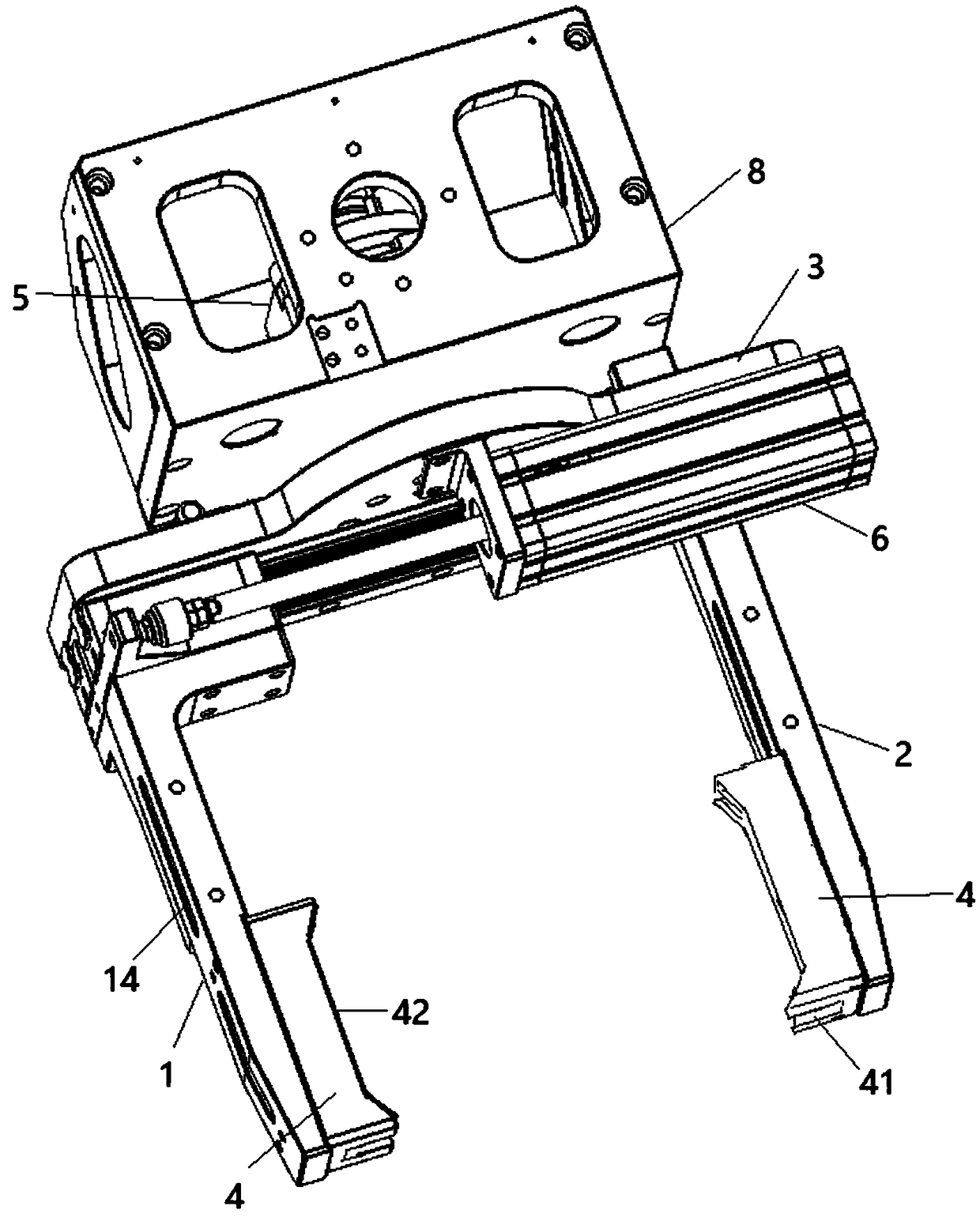
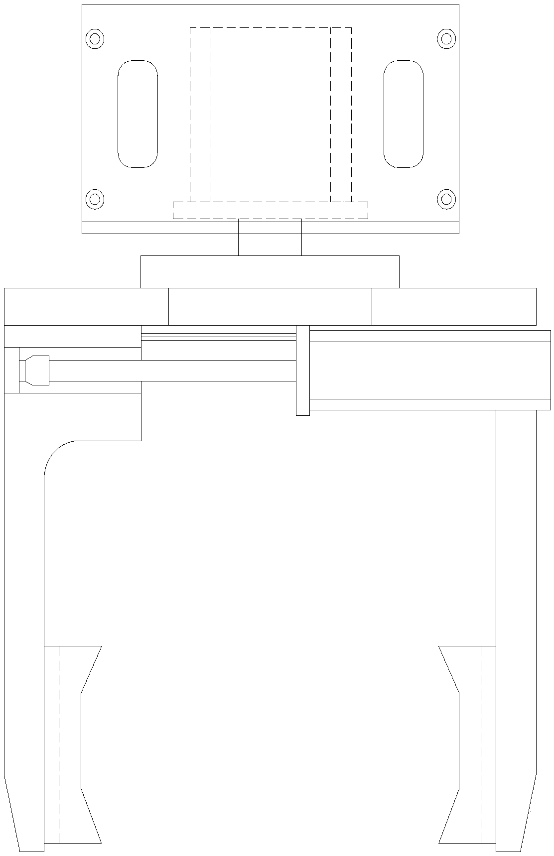
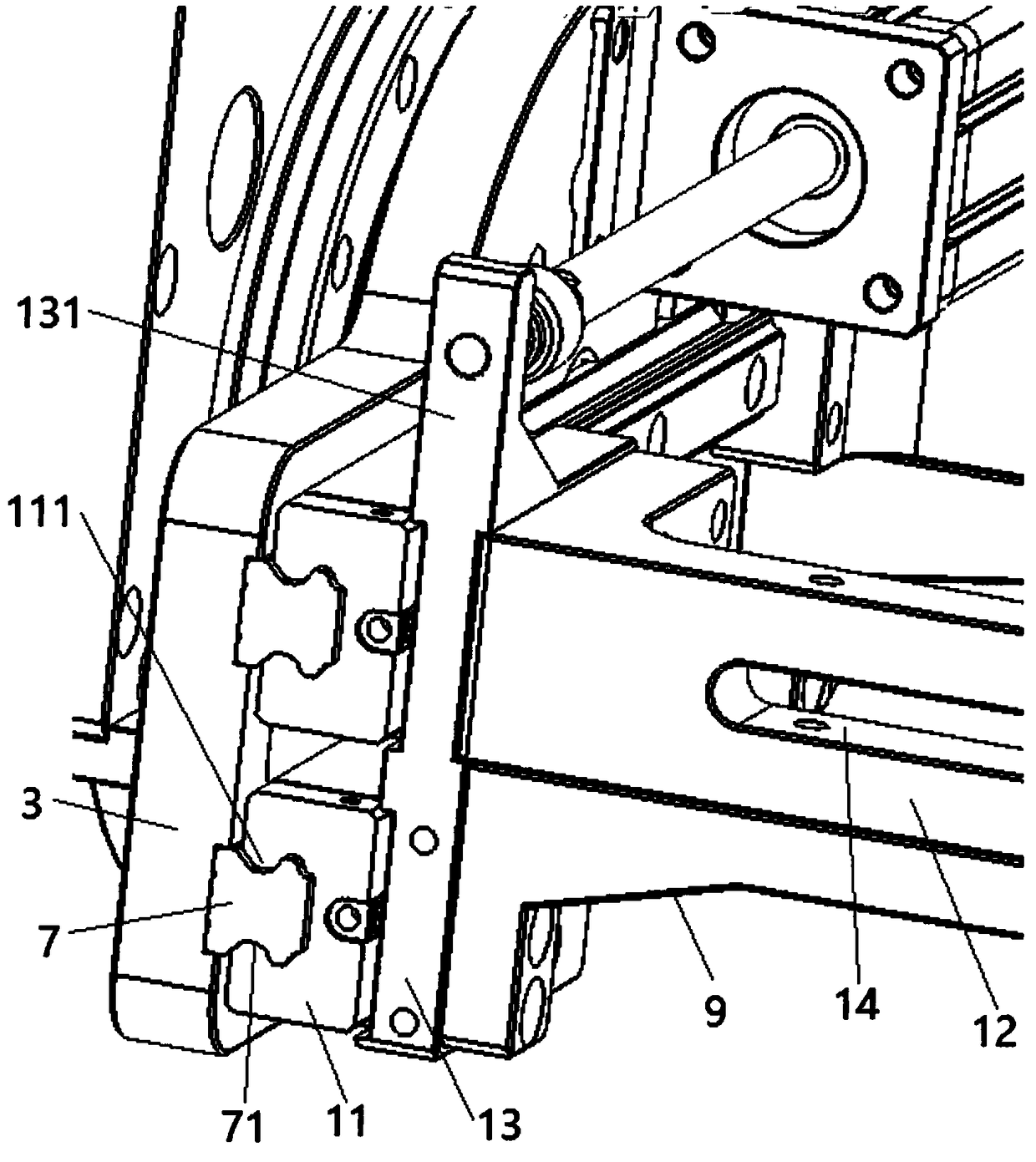
[0020] Such as Figure 1 to Figure 3 As shown, a multi-purpose manipulator clamp includes a left clamp arm 1, a right clamp arm 2 and a cross arm 3 vertically connecting the left clamp arm 1 and the right clamp arm 2, and the right clamp arm 2 and the cross arm 3 are fixedly connected , the left clamping arm 1 is slidably connected with the cross arm 3, and the inner sides of the left clamping arm 1 and the right clamping arm 2 are respectively provided with two opposite clamping blocks 4, and the two clamping blocks 4 are respectively provided with a card slot 41, and the card slot 41 The clamping block 4 runs through the direction parallel to the left clamping arm 1 and the right clamping arm 2, and the opening ends of the two clamping grooves 41 are oppositely arranged, and the clamping grooves 41 can be used to fork objects with ribs on both sides; this embodiment also Including the second drive cylinder 5, the second drive cylinder 5 is connected to the side of the cross ...


PUM


Abstract

The invention provides a multi-purpose mechanical hand clamp. The multi-purpose mechanical hand clamp comprises a left clamping arm, a right clamping arm and a transverse arm. The right clamping arm is fixedly connected with the transverse arm, and the left clamping arm is connected with the transverse arm in a sliding mode. Two clamping blocks which are arranged in a face-to-face mode are arranged on the inner sides of the left clamping arm and the right clamping arm correspondingly, clamping grooves are formed in the two clamping blocks, and the opening ends of the two clamping grooves are arranged in a face-to-face mode. The multi-purpose mechanical hand clamp further comprises a second driving cylinder. The second driving cylinder is located on the side, far away from the left clampingarm and the right clamping arm, of the transverse arm, and an output shaft of the second driving cylinder is connected with the transverse arm. A first driving cylinder and sliding rails are installed on the transverse arm, an output shaft of the first driving cylinder is connected with the left clamping arm, sliding blocks which are matched with the structures of the sliding rails are fixedly arranged at the front end of the left clamping arm, and the first driving cylinder can drive the left clamping arm to move along the sliding rails. By the adoption of the multi-purpose mechanical hand clamp, the clamping arms can be stretched or combined to clamp an object, an object with convex edges on the two sides can be forked by the clamping grooves of the clamping blocks on the clamping arms,and the multi-purpose mechanical hand clamp has the clamping and forking purposes and is broad in application range.

Description

technical field [0001] The invention belongs to the technical field of mechanical equipment, and in particular relates to a multipurpose manipulator clamp. Background technique [0002] A manipulator is an auxiliary device used for material handling or installation. It ingeniously applies the balance principle of force, so that the object can move in balance according to the set distance and orientation in the space, and the heavy object can be correctly placed in the set position in the space without laborious and skilled manual operation. The manipulator clamp is an important part of the power-assisted manipulator, which is used to grab the workpiece. Existing grippers for manipulators usually only have clamp arms that can be opened or closed to pick up objects, while some objects have protruding edges on both sides, and the contact area between the edges and the clamp arms is small, resulting in objects being clamped Shaking between the arms prevents the object from bei...

Claims


Application Information

Patent Timeline
IPC IPC(8): B25J15/00B25J15/08
CPCB25J15/00B25J15/0023B25J15/08
Inventor 王三祥朱士新
Owner JIANGSU YUBO AUTOMATION EQUIP CO LTD
Why Eureka
Try Eureka