
Azimuth imaging method for mimo arc array in terahertz frequency band

An arc-shaped array and imaging method technology, applied in the field of signal processing, can solve the problems of reducing the imaging distance and increasing the length of the array, and achieve the effect of reducing system cost

Active Publication Date: 2021-11-23
INST OF ELECTRONICS CHINESE ACAD OF SCI
View PDF5 Cites 0 Cited by
  • Summary
  • Abstract
  • Description
  • Claims
  • Application Information

AI Technical Summary

Problems solved by technology

In order to obtain higher azimuth resolution, it is necessary to increase the array length or reduce the imaging distance, which is restricted by the array element spacing

Method used


Image

  • Azimuth imaging method for mimo arc array in terahertz frequency band
  • Azimuth imaging method for mimo arc array in terahertz frequency band
  • Azimuth imaging method for mimo arc array in terahertz frequency band

Examples


Embodiment Construction

[0056] In order to make the object, technical solution and advantages of the present invention clearer, the present invention will be further described in detail below in conjunction with specific embodiments and with reference to the accompanying drawings.

[0057] It should be noted that, in the drawings or descriptions of the specification, similar or identical parts all use the same figure numbers. Implementations not shown or described in the accompanying drawings are forms known to those of ordinary skill in the art. Additionally, while illustrations of parameters including particular values ​​may be provided herein, it should be understood that the parameters need not be exactly equal to the corresponding values, but rather may approximate the corresponding values ​​within acceptable error margins or design constraints. In addition, the directional terms mentioned in the following embodiments, such as "upper", "lower", "front", "rear", "left", "right", etc., are only re...


PUM


Abstract

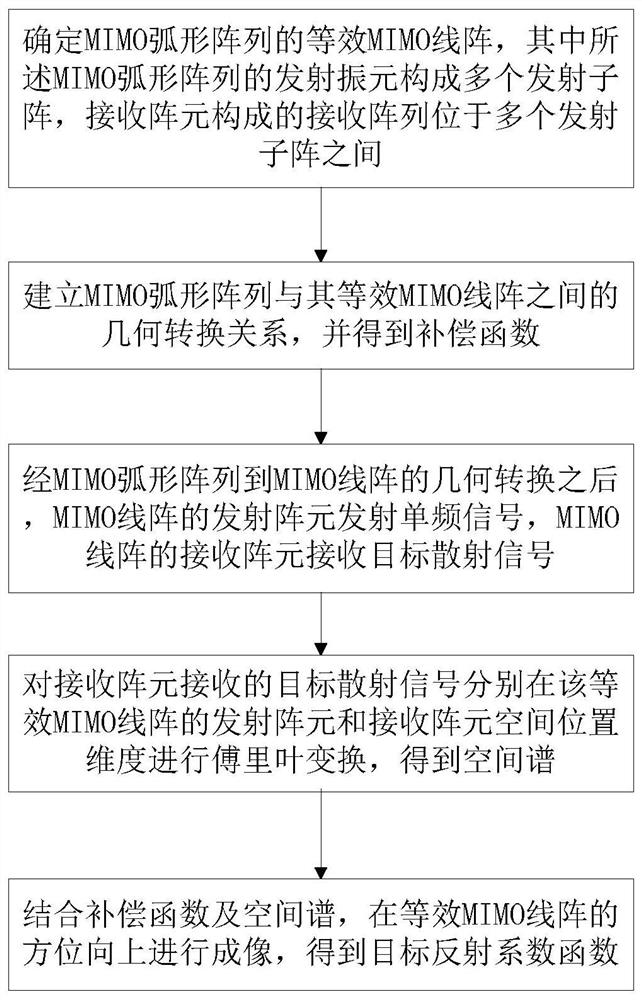
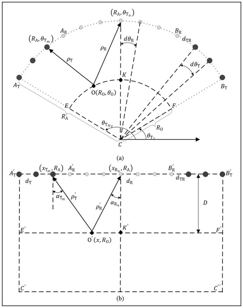
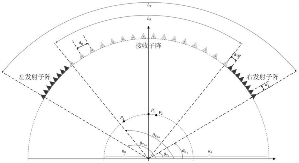
The present invention provides an azimuth imaging method for a MIMO arc array in the terahertz frequency band, comprising: determining the equivalent MIMO line array of the MIMO arc array, the transmitting array elements of the MIMO arc array forming a plurality of transmitting sub-arrays, receiving The receiving array composed of array elements is located between multiple transmitting sub-arrays; the geometric conversion relationship between the MIMO arc array and the MIMO linear array is established to obtain the compensation function; the transmitting array elements of the MIMO linear array transmit single-frequency signals, and the receiving array of the MIMO linear array The element receives the scattered signal of the target; the Fourier transform is performed on the received signal in the spatial position dimension of the transmitting array element and the receiving array element to obtain the spatial spectrum; combined with the compensation function and the spatial spectrum, imaging is carried out in the azimuth direction of the equivalent MIMO linear array, and the obtained Target reflectance function. The present invention realizes high-efficiency azimuth imaging by constructing an arc-shaped MIMO array and using fewer array elements under a certain array length, and provides the possibility of reducing system cost.

Description

technical field [0001] The invention relates to the technical field of signal processing, in particular to an azimuth imaging method for MIMO arc arrays in the terahertz frequency band. Background technique [0002] In the application of MIMO array imaging, the imaging method is obviously an extremely important link, because the accuracy and efficiency of the imaging method largely determine the quality of the imaging results and the operating speed of the system. The design of the MIMO array azimuth imaging method is mainly to effectively solve the relationship between the array length, the number of array elements and the azimuth resolution under certain MIMO array topological structure conditions, and at the same time take into account the computational efficiency. The array length and the number of array elements directly determine the array element spacing, that is, determine the spatial sampling rate. When it satisfies the Nyquist sampling law, azimuth imaging will not...

Claims


Application Information

Patent Timeline
Patent Type & Authority Patents(China)
IPC IPC(8): G01S17/89
CPCG01S17/89
Inventor 吴世有李超张群英高航刘小军方广有
Owner INST OF ELECTRONICS CHINESE ACAD OF SCI
Learn More