
A circular automatic access parking device on the upper layer of the road

An automatic access and parking device technology, which is applied in the direction of buildings, building types, buildings, etc. where cars are parked, can solve the problems of complex structure, low efficiency of vehicle parking and transfer, and low space utilization, and achieve simple and stable structure, convenient Intelligent control and high space utilization

Active Publication Date: 2020-07-28
CHANGZHOU INST OF TECH
View PDF1 Cites 0 Cited by
  • Summary
  • Abstract
  • Description
  • Claims
  • Application Information

AI Technical Summary

Problems solved by technology

[0010] The purpose of the present invention is to overcome the shortcomings of existing mechanical parking devices such as complex structure, low vehicle parking and transfer efficiency, and low space utilization, and provide a ring-shaped automatic access parking device on the upper layer of the road. The vehicle is parked and retrieved by the structure, and the vehicle can be moved and exchanged on the parking platform according to the planned circular route through the translation and lifting movement of the vehicle-carrying plate. The structure is simpler and more stable, and it is convenient for intelligent control. Higher, safe and reliable vehicle parking, and higher parking efficiency; at the same time, it adopts modular design, which can realize various changes according to the site environment, facilitates standardized large-scale production, convenient assembly, low manufacturing cost, strong practicability, and is conducive to widespread promotion

Method used


Image

  • A circular automatic access parking device on the upper layer of the road
  • A circular automatic access parking device on the upper layer of the road
  • A circular automatic access parking device on the upper layer of the road

Examples


Embodiment 1

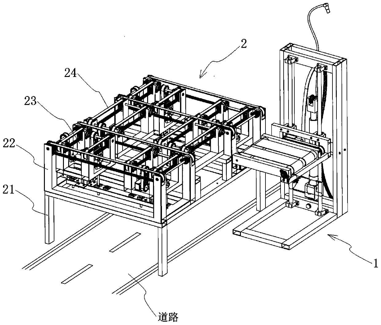
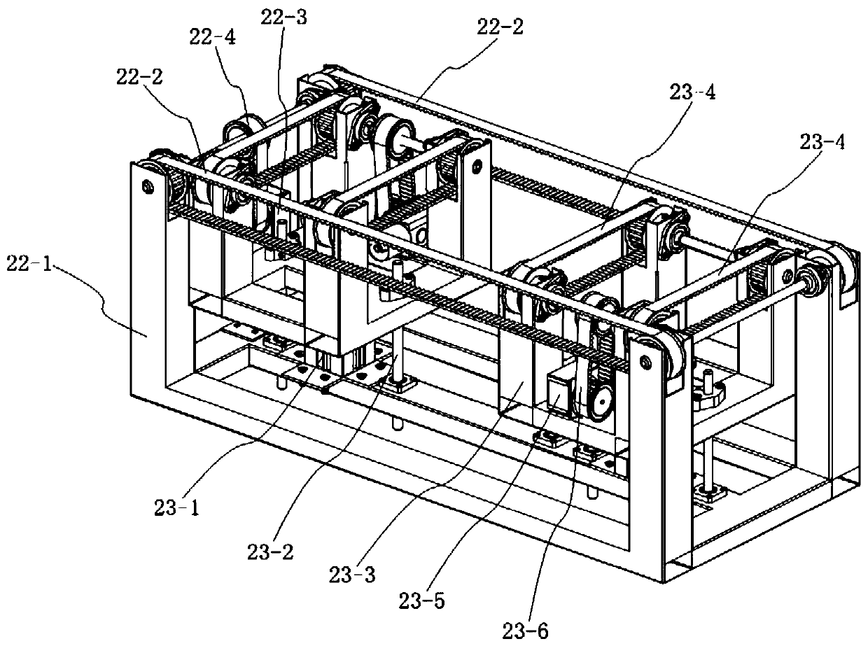
[0047] combine Figure 1 to Figure 7 As shown, a ring-shaped automatic access parking device for the upper layer of the road of the present embodiment includes a parking lifting device 1, a parking platform assembly 2 and a vehicle loading plate, the parking platform assembly 2 is a rectangular structure, and the parking platform assembly 2 The support frame 21 is erected on the upper layer of the road. The support frame 21 is the foundation of the entire parking platform assembly 2 and has sufficient structural strength and load-bearing capacity. The parking platform assembly 2 can be erected above the slow lane or community sidewalk through the support frame 21. It does not affect the traffic below, of course, the parking space or road green belt can also be used below the parking platform assembly 2. According to specific needs, the parking platform assembly 2 can be designed as one floor or multiple layers. The rectangular side positions of the parking platform assembly 2...

Embodiment 2

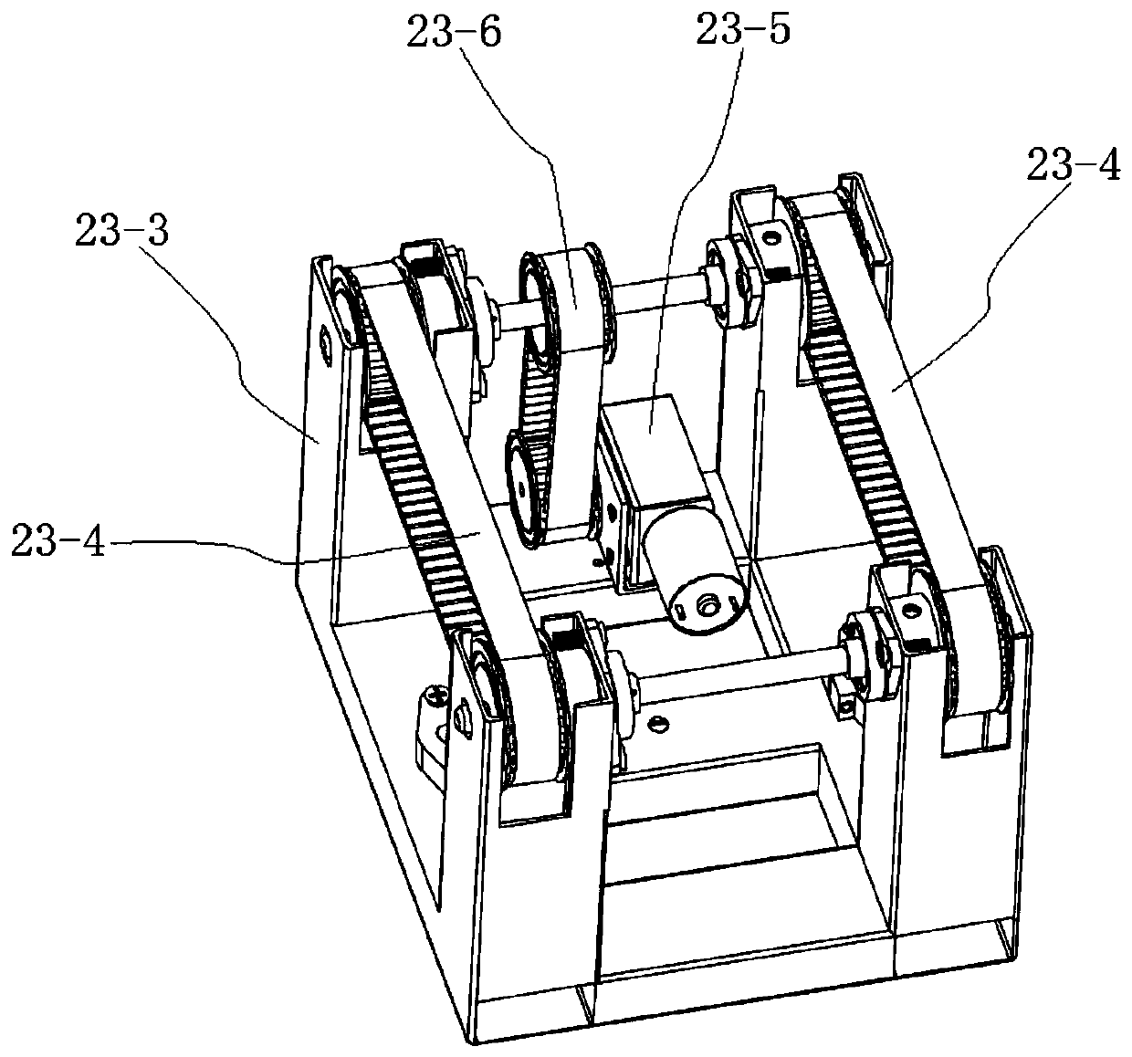
[0053] combine Figure 1 to Figure 6 As shown, a ring-shaped automatic access parking device for the upper layer of the road in this embodiment includes a parking lifting device 1, a parking platform assembly 2 and a vehicle-carrying plate, and the specific structures of the parking lifting device 1 and the vehicle-carrying plate are the same as those in the embodiment 1. The difference is that the parking platform assembly 2 has a rectangular structure, and the parking platform assembly 2 is erected on the upper layer of the road through the support frame 21, and the parking platform assembly 2 has two rows of parking spaces that can carry vehicles through the vehicle-carrying plate. And each row has more than two parking stalls, and the two rows of parking stalls are all provided with a transverse conveying mechanism 22-2 for driving the vehicle-carrying plate to move laterally. Each parking space is provided with a lifting and reversing module 23 for driving the lifting mov...


PUM


Abstract

The invention discloses a road upper annular automatic access parking device, and belongs to the field of mechanical parking devices. The road upper annular automatic access parking device is characterized in that annular parking spaces are successively arranged on a parking platform assembly of a rectangular structure; horizontal and longitudinal conveying mechanisms for driving vehicle carryingplates for carrying vehicles to translate are arranged on the parking spaces; reversing motion of the vehicle carrying plates can be achieved by using the conveying mechanism which can lift to performreversing; the planar moving structure is used to park and pick the vehicles; the vehicles can move and exchange positions according to a planned annular path on the parking platform through translation and lifting of the vehicle carrying plates; the structure is simple and stable, intelligent control is facilitated, the space utilization rate is high, vehicle parking and picking is safe and reliable, and the parking and picking efficiency is high; and the parking device can be easily mounted above the road, will not affect lower traffic, and is especially suitable for construction in slow lanes and residential areas.

Description

technical field [0001] The invention relates to a parking device, more specifically, to a ring-shaped automatic access parking device on the upper layer of the road. Background technique [0002] With the continuous improvement of the urbanization level and the rapid development of the automobile industry, my country will enter a period of rapid increase in the number of automobiles. At the same time, due to the unreasonable setting of the parking lot, the phenomenon of parking on the road and occupying the green space of the residential area is serious, causing traffic chaos and the problem of "difficult parking" intensified. [0003] At present, flat parking lots are used on a large scale in our cities. The characteristic of this parking method is that it is convenient to park, but it occupies a large area. This area includes the parking area and the lane area required for parking. In addition, the parking lot has regulations on slope, turning radius, and width. On avera...

Claims


Application Information

Patent Timeline
Patent Type & Authority Patents(China)
IPC IPC(8): E04H6/22E04H6/42
CPCE04H6/22E04H6/42
Inventor 倪雪聪杨星言淳朱沈伟黄中银蒋帅杨辉黄亮
Owner CHANGZHOU INST OF TECH
Learn More