Eureka AIR delivers breakthrough ideas for toughest innovation challenges, trusted by R&D personnel around the world.

A pneumatic booster type inter-stage separation mechanism-

A technology of inter-stage separation and pneumatic boosting, which is applied in the direction of motor vehicles, aerospace equipment, and aerospace vehicles, etc., can solve the problems of being in the wake of the upper-stage engine, increasing product costs, and being difficult to adopt, so as to achieve unlocking The separation is simple and easy to realize, the aerodynamic shape is good, and the structure is simple

Active Publication Date: 2018-12-14
XIAN AEROSPACE PROPULSION TECH INST
View PDF10 Cites 5 Cited by
  • Summary
  • Abstract
  • Description
  • Claims
  • Application Information

AI Technical Summary

Problems solved by technology

[0005] (1) The anti-thrust auxiliary power unit used in the separation of multi-stage missiles or rocket stages has a complex structure, and increases the ignition sequence of one way, which reduces reliability. When using this device for inter-stage separation, it will inevitably lead to an increase in product cost
[0006] (2) For the traditional cold separation method, the rapidity of separation mainly depends on the difference in resistance between the two stages, so for missiles or rockets with a small difference in diameter between the two stages, it is often difficult to adopt
[0007] (3) Multi-stage missiles or rockets usually adopt a thermal separation method that relies on the thrust of the upper stage engine. The disadvantage is that the connecting parts between the two stages are always in the wake of the upper stage engine during the separation process, and the stiffness of the connecting parts needs to be considered. , strength, ablation resistance and reliability

Method used


Image

  • A pneumatic booster type inter-stage separation mechanism-
  • A pneumatic booster type inter-stage separation mechanism-
  • A pneumatic booster type inter-stage separation mechanism-

Examples


Embodiment Construction

[0026] The present invention will be described in detail below with reference to the accompanying drawings and examples.

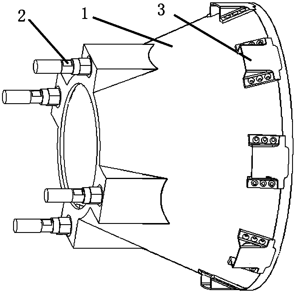
[0027] The invention provides a pneumatic pressurized interstage separation mechanism, such as figure 2 As shown, it includes an interstage compartment shell 1, an explosion bolt 2 and a pressurized cover 3.

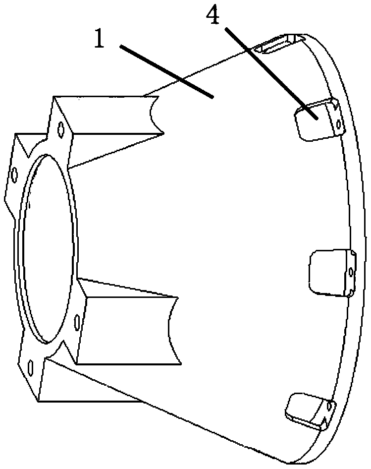
[0028] The interstage cabin shell 1 is located between the upper stage and the lower stage, and its main function is to connect the upper stage and the lower stage as a whole, maintain the aerodynamic shape of the rocket or missile during flight, and meet certain shape, strength and rigidity requirements . The connection surface between the interstage cabin shell 1 and the tail end of the upper stage is the interstage separation surface. The outer wall of the rear end of the interstage cabin shell 1 is uniformly provided with through holes 4 along the circumferential direction.

[0029] Explosive bolts 2 are arranged on the butt joint end surface...


PUM


Abstract

The invention discloses a pneumatic pressurized inter-stage separation mechanism which comprises an inter-stage cabin shell connected with an unlocking device and a pressurized cover. the inter-stagecabin shell is connected to an upper tail end of the unlocking device, a through hole is uniformly arrange along the circumferential direction on the outer wall of the rear end of the inter-stage cabin shell, and the pressurize cover is fixed on the through hole, and the opening faces the windward surface, so as to guide air into the inter-stage cabin and increase the resistance difference. The invention has simple structure, can increase two-stage aerodynamic resistance difference, and realizes reliable separation.

Description

technical field [0001] The invention relates to the technical field of multi-stage missiles or rockets, in particular to a pneumatic pressurized inter-stage separation mechanism. Background technique [0002] For small and medium-sized multi-stage missiles or rockets in a series layout, in order to reduce the speed loss of the missile or rocket and provide a channel for the upper-stage engine to work, after the lower-stage engine has finished working, the lower stage must be thrown away as soon as possible, that is, Achieve separation between stages. A typical tandem two-stage rocket layout is shown in figure 1 . [0003] According to the published information, there are two commonly used interstage separation methods at present. One is the thermal separation method, that is, after the work of the lower stage engine is completed, the mechanism connecting the front end of the interstage cabin to the upper stage is unlocked, and the upper stage engine is released at the same...

Claims


Application Information

Patent Timeline
IPC IPC(8): B64G1/64
CPCB64G1/645
Inventor 李晓晖王小妮郑佩程养民张兵峰吴俊全张菲
Owner XIAN AEROSPACE PROPULSION TECH INST
Why Eureka
Eureka Blog
Learn More