
Robot finger mechanism

A robot finger and machine base technology, which is applied in the field of robots, can solve the problems of large volume, complex structure, and difficulty in meeting the requirements of small operating space for robot fingers, and achieve the effect of simple and compact structure, less number of drives, and easy control

Active Publication Date: 2018-12-14
YANSHAN UNIV
View PDF23 Cites 6 Cited by
  • Summary
  • Abstract
  • Description
  • Claims
  • Application Information

AI Technical Summary

Problems solved by technology

Although the above-mentioned patents have improved the bearing capacity and rotation accuracy of the robot finger, the structure is r

Method used


Image

  • Robot finger mechanism
  • Robot finger mechanism

Examples


Embodiment Construction

[0014] The following will clearly and completely describe the technical solutions in the embodiments of the present invention with reference to the accompanying drawings in the embodiments of the present invention. Obviously, the described embodiments are only some, not all, embodiments of the present invention. Based on the embodiments of the present invention, all other embodiments obtained by persons of ordinary skill in the art without making creative efforts belong to the protection scope of the present invention.

[0015] The purpose of the present invention is to provide a robotic finger mechanism to solve the problems in the prior art above, so that the fingers can sense the grasping force while having the ability to grasp flexibly, safely and with large loads.

[0016] In order to make the above objects, features and advantages of the present invention more comprehensible, the present invention will be further described in detail below in conjunction with the accompany...


PUM


Abstract

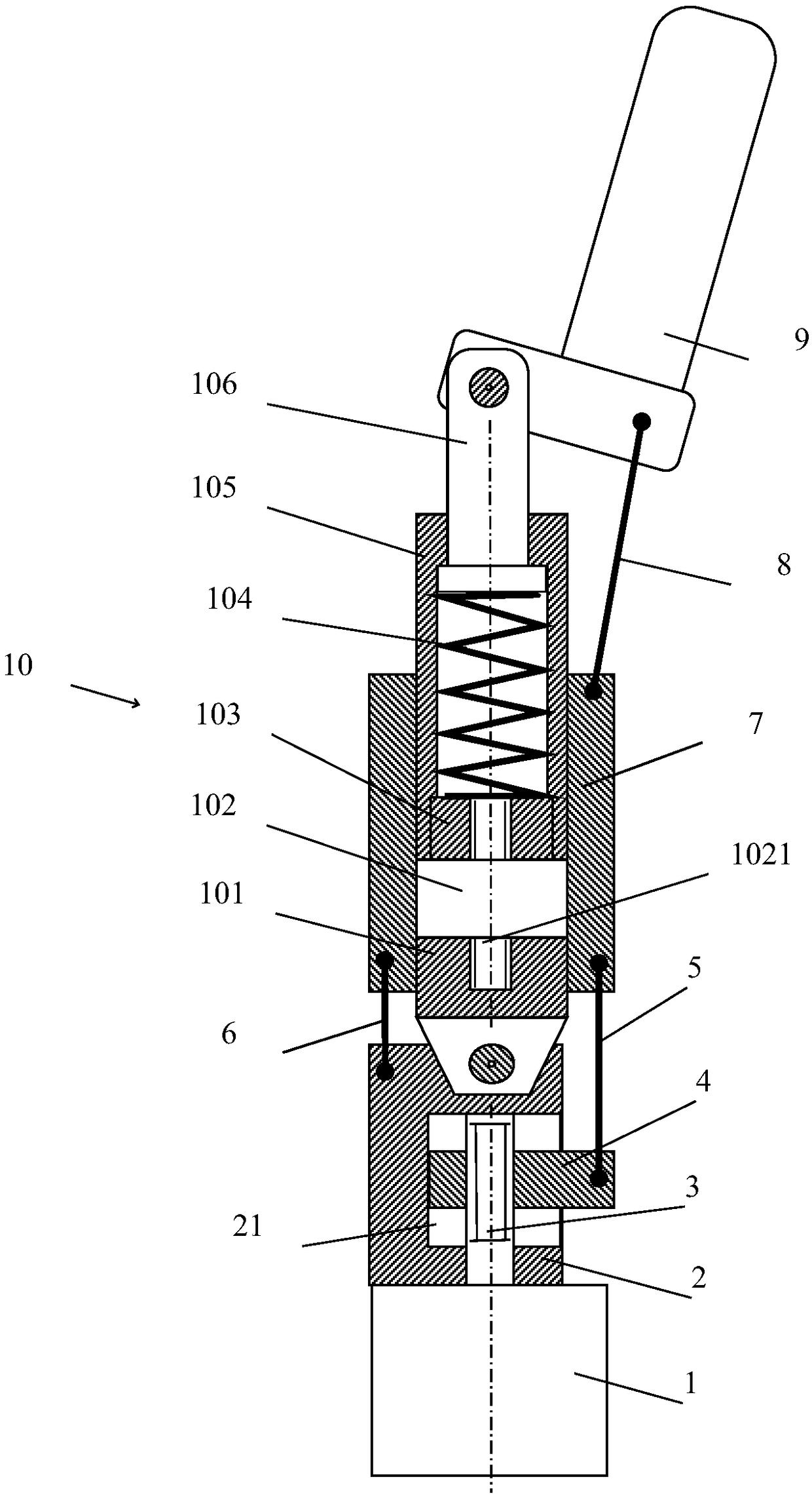
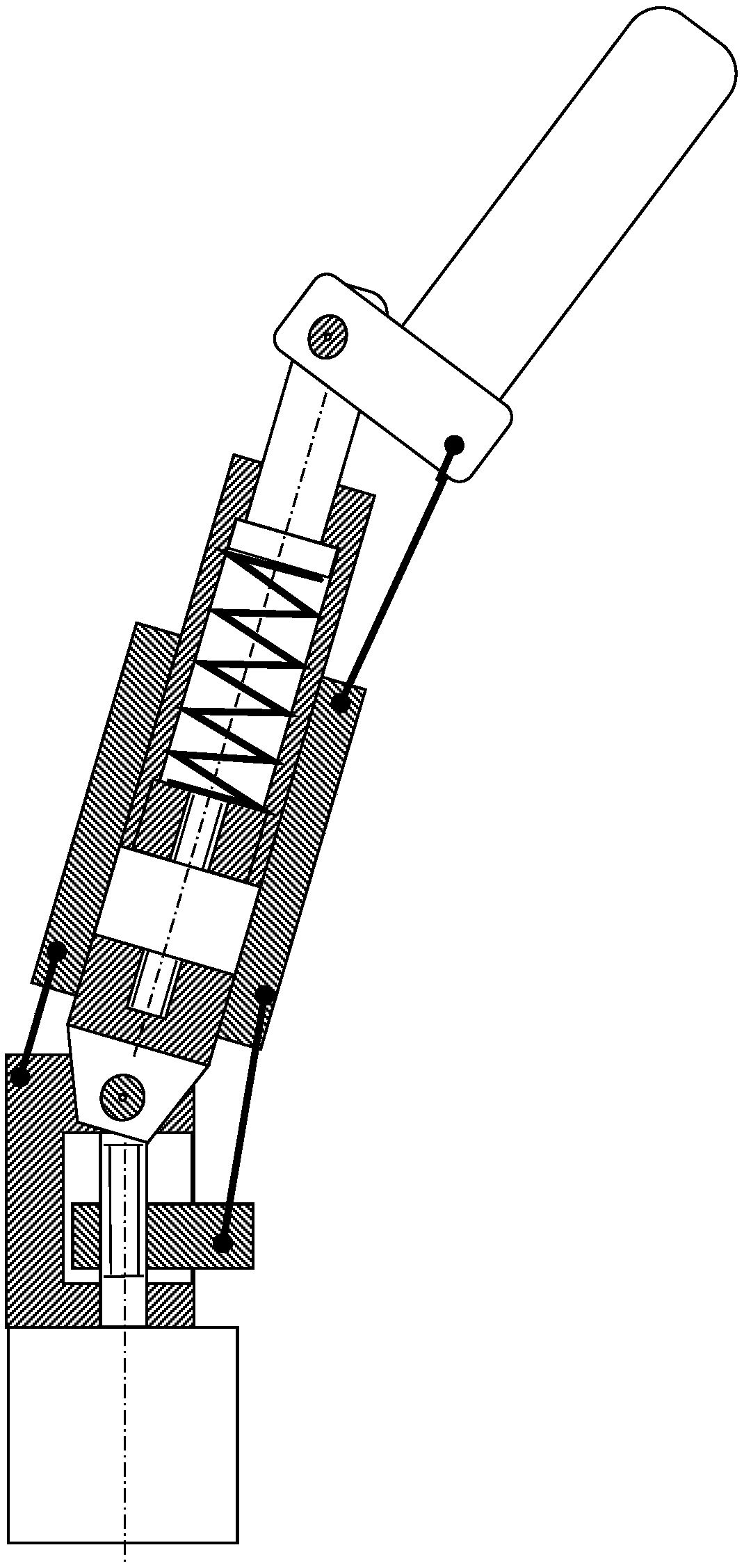
The invention discloses a robot finger mechanism. The robot finger mechanism comprises a motor, a lead screw, a machine base, a nut, a sleeve, an upper rod, a lower rod, an outer side rod, a flexibleforce measuring rod set and a swing finger, the flexible force measuring rod set comprises an upper shaft, a guide sleeve, a spring, an end cover, a force sensor and a lower shaft, and the flexible force measuring rod set slides in the sleeve; one end of the upper shaft and the spring are arranged in the cavity of the guide sleeve, the two ends of the upper shaft are rotationally linked with the swing finger and are slidably linked with the guide sleeve correspondingly, and the other end of the guide sleeve is fixedly connected with the end cover; the two ends of the spring abut against a large cylinder of the upper shaft and the end cover, the two ends of the force sensor are fixedly connected with the end cover and the lower shaft correspondingly, and the other end of the lower shaft isrotationally linked with the machine base; the two ends of the lower rod are correspondingly linked with the nut and the sleeve in a rotating mode, the two ends of the side rod are correspondingly androtationally linked with the machine base and the sleeve, and the two ends of the upper rod are rotationally linked with the sleeve and the swing finger correspondingly; and the motor drives the nutto slide in a machine base guide groove so that the robot finger can be bent or opened. According to the robot finger mechanism, the flexible, safe and large-load grabbing capacity is achieved while the grabbing force is sensed.

Description

technical field [0001] The invention relates to the technical field of robots, in particular to a robot finger mechanism. Background technique [0002] The robot finger mechanism refers to the device installed at the end of the robot arm and directly acts on the working object. All kinds of operations to be completed by industrial robots must be realized by fingers. The structure, weight, and size of the fingers have a direct and significant impact on the overall kinematics and dynamics of the robot. Finger design is an important link in robot hand design. With the development of robot technology, various forms of robot fingers have emerged. Fingers are generally rigid, and the grasping surface forms a depression or a v-shaped groove according to the envelope of the object shape. At present, the drive of the robot finger mechanism is divided into tendon rope traction drive, rigid link drive and pneumatic drive. Due to the compact structure of tendon rope traction and dri...

Claims


Application Information

Patent Timeline
IPC IPC(8): B25J15/00B25J15/02B25J19/02
CPCB25J15/0009B25J15/0206B25J19/02
Inventor 路懿常泽锋路扬
Owner YANSHAN UNIV
Learn More