
Gravity balancing mechanism

A gravity balance and pulley technology, applied in the field of medical machinery, can solve the problems of limited output force, large counterweight mass, limited output force, etc., and achieve the effects of long output stroke, stable output force, and large output force value.

Active Publication Date: 2018-12-14
NEUSOFT MEDICAL SYST CO LTD
View PDF13 Cites 0 Cited by
  • Summary
  • Abstract
  • Description
  • Claims
  • Application Information

AI Technical Summary

Problems solved by technology

[0004] The first is counterweight balance, using counterweights with the same mass or doubled mass to offset the gravity of the tube image receiver. The advantage is that the gravity in the vertical state can be accurately offset. The object moves synchronously, the structure is complex and the stroke is limited
[0005] The second is to use variable-diameter pulleys to convert the force of the tension spring into a relatively stable output force. The disadvantage is that when the output force of the tension spring is large, the size of the structure itself will increase accordingly, and the structure is greatly restricted, resulting in output Force limitation
[0006] The third is to use a spring balancer, which uses the curling and relaxation of the coil spring and the variable diameter pulley to output relatively stable force. The advantage is that the structure is compact, and the disadvantage is that the life is short and the output force is limited. Generally, it is only used for Counteracts when gravity is low

Method used


Image

  • Gravity balancing mechanism
  • Gravity balancing mechanism
  • Gravity balancing mechanism

Examples


Embodiment Construction

[0022] Reference will now be made in detail to the exemplary embodiments, examples of which are illustrated in the accompanying drawings. When the following description refers to the accompanying drawings, the same numerals in different drawings refer to the same or similar elements unless otherwise indicated. The implementations described in the following exemplary examples do not represent all implementations consistent with the present invention. Rather, they are merely examples of apparatuses and methods consistent with aspects of the invention as recited in the appended claims.

[0023] Below in conjunction with accompanying drawing, the gravity balance mechanism of the present invention is introduced in detail.

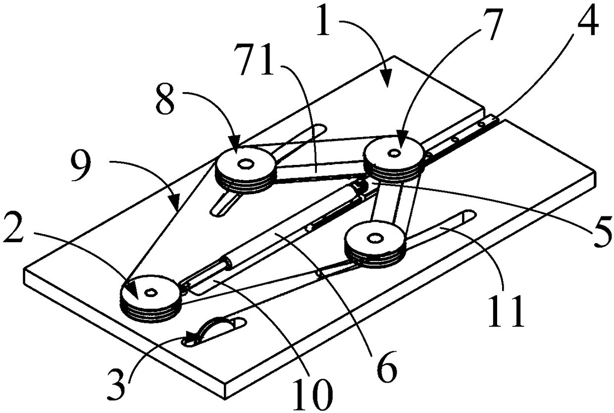
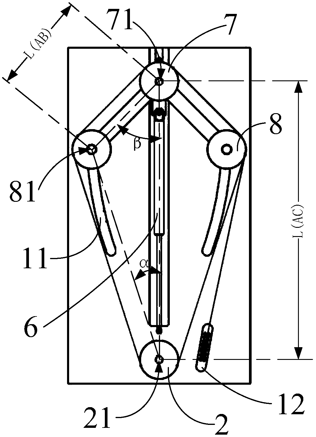
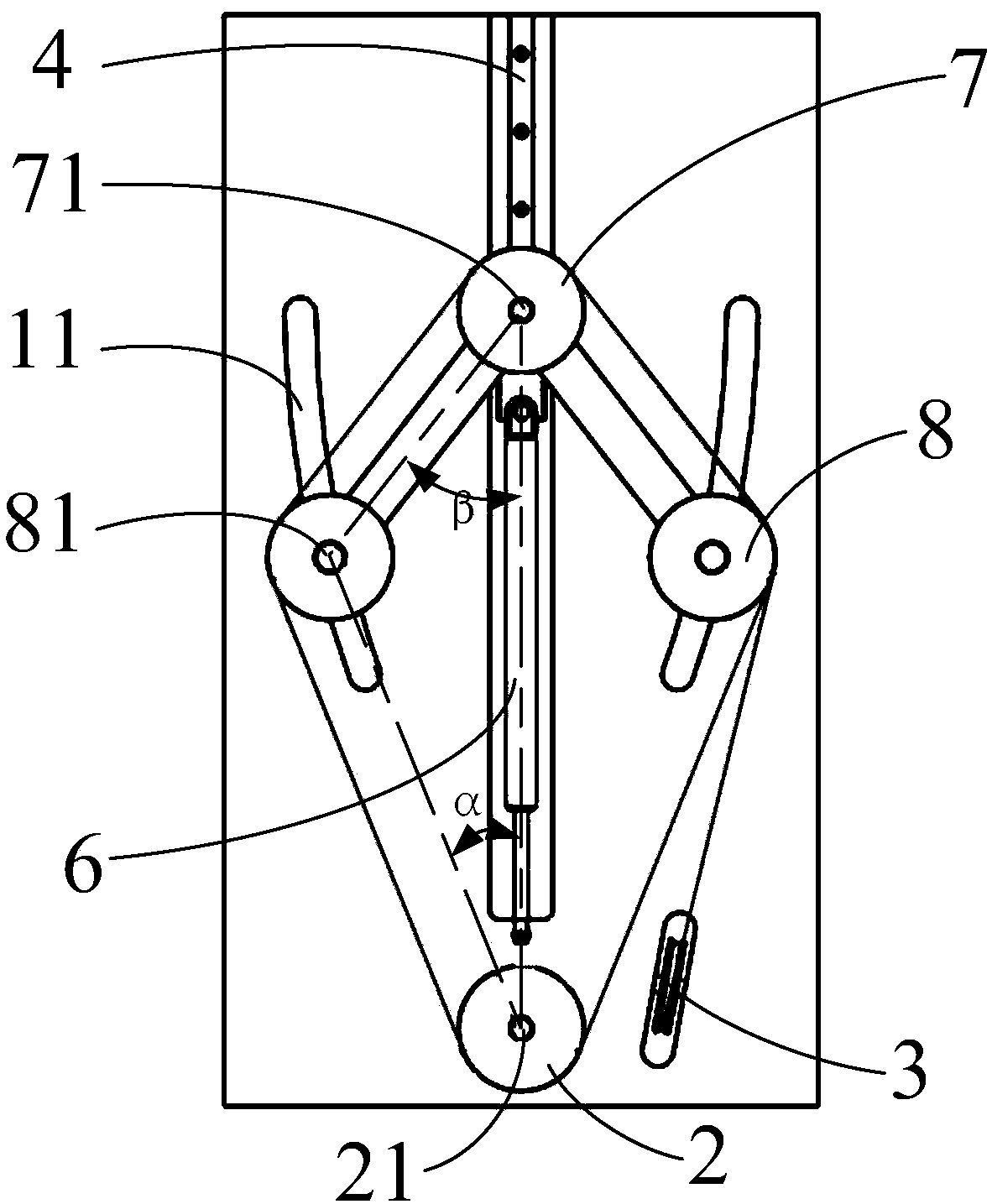
[0024] see Figure 1 to Figure 3 As shown, the gravity balance mechanism of the present invention includes a base 1, a fixed pulley 2 fixed on the base 1, a reversing pulley 3 and a linear slide rail 4, a slider 5 sliding on the linear slide rail 4, and a slid...


PUM


Abstract

The invention provides a gravity balancing mechanism. The mechanism comprises a pedestal, a fixed pulley, a reversing pulley, a slide block, an elastic component, a moving pulley, one pair of connection rods, one pair of side pulleys and a steel wire rope, wherein the fixed pulley and the reversing pulley are fixed to the pedestal; the slide block slides relative to the pedestal; the elastic component abuts against the slide block; the moving pulley is fixed to the slide block; one pair of connection rods is connected to the moving pulley; one pair of side pulleys is connected to the connection rods; and the steel wire rope winds the reversing pulley, the side pulleys, the moving pulley and the fixed pulley. The fixed pulley, the moving pulley and the side pulleys are fixed through a firstshaft, a second shaft and a third shaft and can be rotated around the first shaft, the second shaft and the third shaft. The pedestal is provided with a pair of guide grooves. The guide grooves are symmetrically arranged relative to the elastic component. The third shaft is in the guide groove and forms rolling contact with an inner wall. The connection rods can be rotated about the second shaftand the third shaft.

Description

technical field [0001] The invention relates to the technical field of medical machinery, in particular to a gravity balance mechanism in DR equipment. Background technique [0002] DR (Digital Radiography) equipment is the abbreviation of digital direct imaging system. Compared with traditional X-ray imaging, it has the advantages of clearer image, lower radiation dose, faster inspection speed and higher inspection success rate. Generally, the ball tube of DR equipment or the image receiver on the column needs to move up and down along a straight line. In order to achieve labor-saving and stable manual lifting or electric lifting, a gravity balance mechanism is usually used to offset the gravity of the ball tube or image receiver, making the movement more labor-saving and more convenient to control. [0003] There are several ways to counteract gravity in general gravity balance mechanism: [0004] The first is counterweight balance, using counterweights with the same mas...

Claims


Application Information

Patent Timeline
Patent Type & Authority Applications(China)
IPC IPC(8): A61B6/00
CPCA61B6/4429A61B6/447
Inventor 孙俊杰
Owner NEUSOFT MEDICAL SYST CO LTD
Learn More