Network equipment fault detection method and device

A network equipment and fault detection technology, applied in the field of network management, can solve problems such as fault false alarms, detection errors, sudden increase or sudden drop in packet traffic, etc., to achieve the effect of improving speed, avoiding one-sided inspection and accurate detection.

Active Publication Date: 2018-12-11
NEW H3C TECH CO LTD
View PDF6 Cites 15 Cited by
  • Summary
  • Abstract
  • Description
  • Claims
  • Application Information

AI Technical Summary

Problems solved by technology

[0003] The above technical means of fault detection treats the traffic data of each port of the network device as separate data and processes them separately. In theory, it can detect the fault of the network device, but in many complex or changing network scenarios, detection will occur. In the event of a mistake, for example, when a service change occurs, the path of the packet flow will be adjusted. At this time, the packet flow of a certain physical port will increase or decrease suddenly. Using the above technical means will obviously cause false alarms. Happening
For another example, if a core device connected to a network device fails, the drop in traffic on it will lead to a significant drop in the packet flow of other network devices connected to it
At this time, the network management platform reports a large number of fault alarms, making it impossible to quickly find the faulty network device, reducing the efficiency of fault detection and troubleshooting
[0004] In summary, existing technologies cannot accurately and quickly detect faulty network devices

Method used


Image

  • Network equipment fault detection method and device
  • Network equipment fault detection method and device
  • Network equipment fault detection method and device

Examples


Embodiment 1

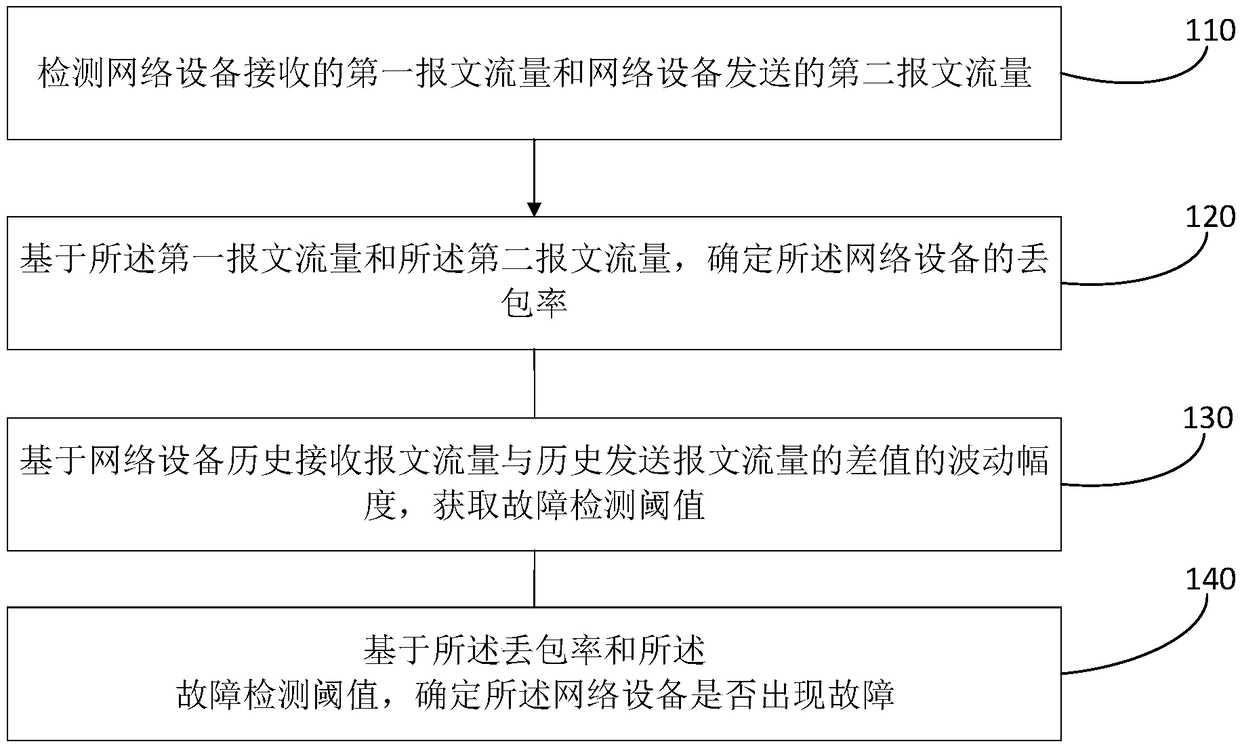
[0058] This embodiment provides a network device fault detection method, which detects faults based on the packet loss rate of the network device, the fluctuation range of the difference between the historical received message traffic and the historical sent message traffic of the network device, and can effectively avoid problems with In the case of other equipment transmitting messages in the current network equipment, when a failure occurs, the impact on the fault detection accuracy of the current network equipment effectively improves the accuracy and adaptability of the network equipment fault detection. Specifically, such as figure 1 As shown, the network equipment fault detection method of the present embodiment includes the following steps:

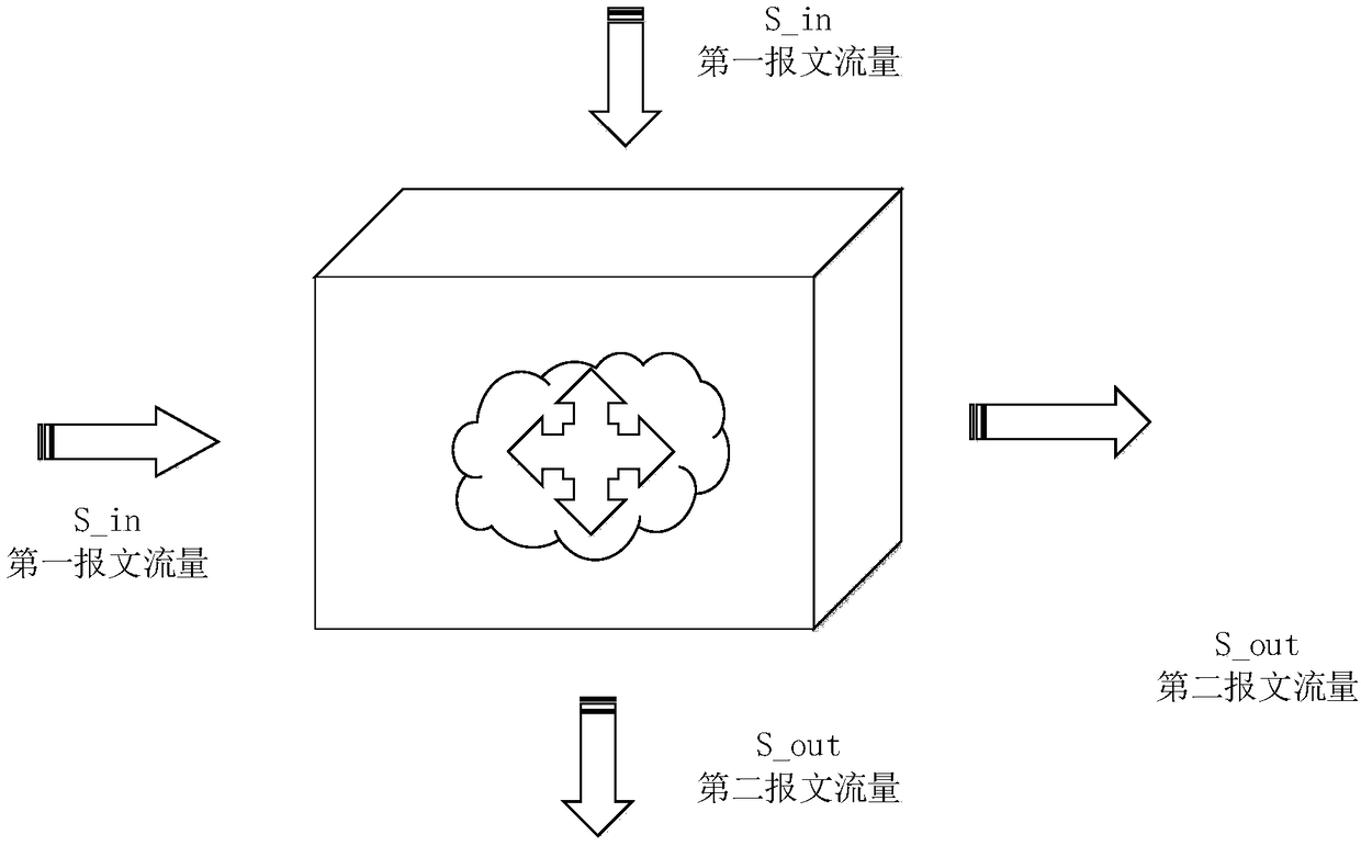
[0059] S110. Detect the first packet flow received by the network device and the second packet flow sent by the network device.

[0060] Here, the network device may be a device with multiple physical ports, such as a switch and ...

Embodiment 2

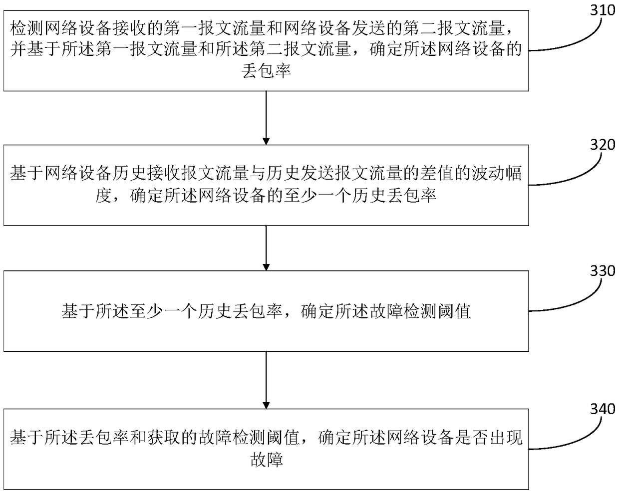
[0081] This embodiment provides a network device fault detection method, which discloses a technical solution for determining a fault detection threshold according to the historical total received traffic and total sent traffic of the network device. Specifically, such as image 3 As shown, the network equipment fault detection method of the present embodiment includes the following steps:

[0082] S310. Detect the first packet flow received by the network device and the second packet flow sent by the network device, and determine the packet loss rate of the network device based on the first packet flow and the second packet flow .

[0083] S320. Determine at least one historical packet loss rate of the network device based on a fluctuation range of a difference between historically received packet traffic and historically sent packet traffic of the network device.

[0084] Here, the historical received message traffic may be all physical ports of the network device, the sum...

Embodiment 3

[0104] This embodiment provides a network device fault detection method, which discloses a technical solution for determining a fault detection threshold according to a historical packet loss rate. Specifically, such as Figure 4 As shown, the network equipment fault detection method of the present embodiment includes the following steps:

[0105] S410. Detect the first packet flow received by the network device and the second packet flow sent by the network device, and determine the packet loss rate of the network device based on the first packet flow and the second packet flow .

[0106] S420. Determine at least one historical packet loss rate of the network device based on a fluctuation range of a difference between historically received packet traffic and historically sent packet traffic of the network device.

[0107] S430. Select the largest historical packet loss rate and the second largest historical packet loss rate.

[0108] S440. Determine the fault detection thr...


PUM


Abstract

Embodiments of the present application provide a network equipment fault detection method and device. The packet loss rate of the network equipment is determined based on a first packet flow receivedby the network device and a second packet flow sent by the network device. Then, the fault detection threshold is obtained based on the fluctuation amplitude of the difference between the history received message flow and the history sent message flow of the network equipment. Finally, based on the packet loss rate and the obtained fault detection threshold, it is determined whether the network equipment fails or not. Compared with the prior art scheme in which the current packet traffic of the utilization port is compared with the historical packet traffic to detect whether a failure has occurred, the technical proposal of the embodiment of the present application can accurately and efficiently detect whether the network equipment fails when the network structure of the network equipmentis changed or other equipment for message transmission with the network equipment fails.

Description

technical field [0001] The present application relates to the technical field of network management, in particular to a network equipment failure detection method and device, and electronic equipment. Background technique [0002] Network device fault detection is very important to timely discover and eliminate network device faults. An efficient network device fault detection mechanism can ensure the normal use of the network by users to the greatest extent. At present, in the practice of network operation and maintenance, the following methods are generally used to detect whether a network device is faulty: first obtain the packet flow of each physical port of the network device, and then compare the packet flow of the current physical port with the historical packet flow of the port For comparison, if the current packet traffic has a significant increase or decrease, it is initially determined that the network device is faulty, and then operation and maintenance personnel...

Claims


Application Information

Patent Timeline
Patent Type & Authority Applications(China)
IPC IPC(8): H04L12/24H04L12/26
CPCH04L41/0631H04L43/0829H04L43/0876H04L43/50
Inventor 王雪
Owner NEW H3C TECH CO LTD
Why Eureka
Try Eureka