
Shaft rotating speed precision measuring system in full rotating speed and measuring method

A technology of precise measurement and shaft speed, applied in the direction of using fluid devices, etc., it can solve the problems of orthogonality damage of the output signal of the photoelectric encoder, torsional vibration or creep of the rotating shaft, and large influence of electromagnetic interference, etc., and achieve good measurement performance. , convenient operation, simple and reasonable structure and novel effect

Pending Publication Date: 2018-12-11
NANJING INST OF TECH +1
View PDF0 Cites 4 Cited by
  • Summary
  • Abstract
  • Description
  • Claims
  • Application Information

AI Technical Summary

Problems solved by technology

[0002] Speed ​​is an important characteristic parameter in performance testing. The determination of many characteristic parameters of power machinery is inseparable from the functional relationship related to speed. Therefore, speed measurement is a key point in various fields of industrial production. At present, the commonly used speed measurement methods at home and abroad are: Electromagnetic type, Hall type, photoelectric type; the electromagnetic type uses the frequency of the induced current generated by cutting the magnetic field lines of the rotor in the rotating magnetic field, and its measurement results are more accurate, but it is greatly affected by electromagnetic interference; the Hall type uses the Hall switch element For measuring the speed, the measurement accuracy depends on the accuracy of the Hall element; the photoelectric method is a non-contact speed measurement method to measure the speed by measuring the frequency or period of the speed signal, but it is very easy to cause torsional vibration of the rotating shaft or Creeping, the orthogonality of the output signal of the photoelectric encoder is destroyed

Method used


Image

  • Shaft rotating speed precision measuring system in full rotating speed and measuring method
  • Shaft rotating speed precision measuring system in full rotating speed and measuring method
  • Shaft rotating speed precision measuring system in full rotating speed and measuring method

Examples


Embodiment Construction

[0016] In order to deepen the understanding of the present invention, the present invention will be described in further detail below in conjunction with the accompanying drawings and embodiments, which are only used to explain the present invention and do not limit the protection scope of the present invention.

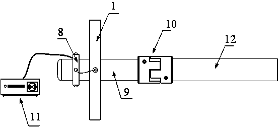
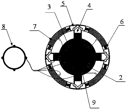
[0017] Such as Figure 1-3 As shown, the present invention is a precision shaft speed measurement system at full speed, and the measurement system includes a measurement device 1, a hub 8, a device main shaft 9, a shaft coupling 10, and a signal processing module 11. The measurement device 1 and The hub 8 is coaxially fixed on the main shaft 9 of the device, the output end of the hub 8 is connected to the signal processing module 11, the main shaft 9 of the device is connected to a rotating shaft 12 through the coupling 10, and the rotating When the shaft 12 rotates at full speed, it drives the main shaft 9 of the device, the measuring device 1 fixed on the main shaf...


PUM


Abstract

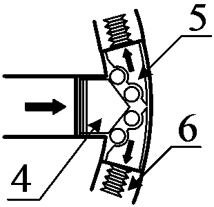
The invention provides a shaft rotating speed precision measuring system in a full rotating speed. The measuring system comprises a measuring device, a wire collector, a device main shaft, a couplingand a signal processing module, the measuring device and the wire collector are coaxially fixed to the device main shaft, an output terminal of the wire collector is connected with the signal processing module, the device main shaft is connected with a rotating shaft through the coupling, the device main shaft and the measuring device and the wire collector fixed to the device main shaft are driven to move in the same rotating speed during full-rotating-speed rotation of the rotating shaft, the measuring device converts the measured rotating speed to an analog quantity voltage signal for output, the voltage signal is acquired by the wire collector, and the signal processing module converts the acquired voltage signal to a corresponding measurement rotating speed and displays the measurement rotating speed. According to the system, a shaft rotating speed precision measuring device, method and system in a full rotating speed is provided based on the centrifugal force effect and the piezoelectric effect, the structure of the device is simple, the method is concise and clear, the system design is reasonable, and good measuring performance is achieved for the rotating speed of the rotating shaft in the full rotating speed.

Description

technical field [0001] The invention belongs to the technical field of rotational speed measurement, and in particular relates to a shaft rotational speed precision measurement device system and a measurement method under full rotational speed. Background technique [0002] Speed ​​is an important characteristic parameter in performance testing. The determination of many characteristic parameters of power machinery is inseparable from the functional relationship related to speed. Therefore, speed measurement is a key point in various fields of industrial production. At present, the commonly used speed measurement methods at home and abroad are: Electromagnetic type, Hall type, photoelectric type; the electromagnetic type uses the frequency of the induced current generated by cutting the magnetic field lines of the rotor in the rotating magnetic field, and its measurement results are more accurate, but it is greatly affected by electromagnetic interference; the Hall type uses ...

Claims


Application Information

Patent Timeline
IPC IPC(8): G01P3/30
CPCG01P3/30
Inventor 贾丙辉冯勇李钢张敏王建余靖
Owner NANJING INST OF TECH
Learn More