A collision-proof charging pile for charging a new energy vehicle
A new energy vehicle and charging pile technology, applied in electric vehicles, motor vehicles, electric traction, etc., can solve problems such as damage to the internal circuit structure, separation of the charging pile from the ground, damage to the charging pile, etc., to avoid excessive torque effect. , The effect of avoiding secondary accidents and protecting the circuit structure
- Summary
- Abstract
- Description
- Claims
- Application Information
AI Technical Summary
Problems solved by technology
Method used
Image
Examples
Embodiment 1
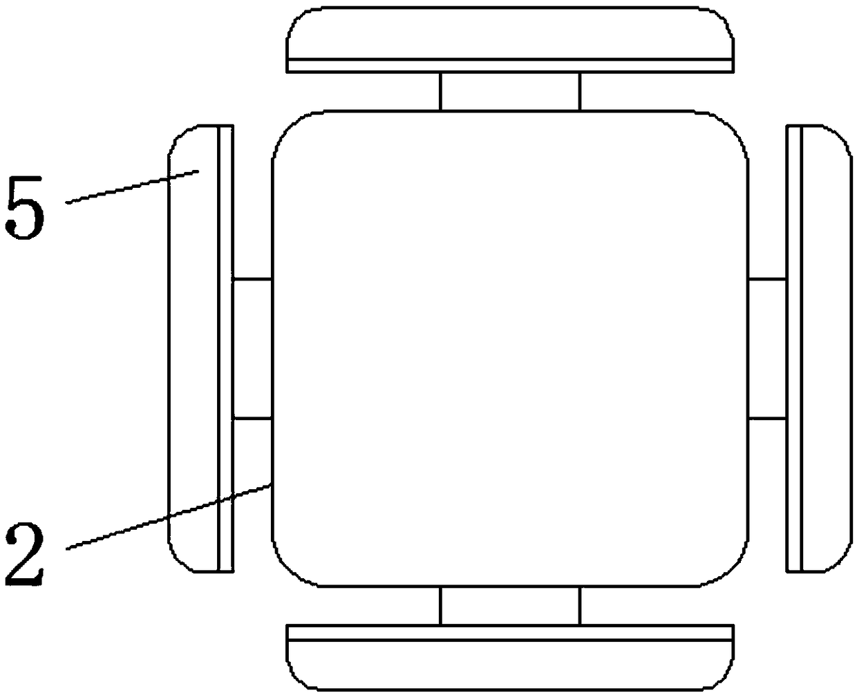
[0027] Embodiment one, with reference to Figure 1-2 , an anti-collision charging pile for charging new energy vehicles, comprising a casing 2, the top of the casing 2 is fixedly connected with a rain-proof roof 1, and the four peripheries of the casing 2 are respectively provided with an elastic curved plate 5, and the elastic The center position of the inner side of the bent plate 5 is elastically connected to the outer wall of the side of the housing 2 through the air spring 7, and the upper and lower ends of the inner side of the elastic bent plate 5 are horizontally welded with a cross bar 8, and one end of the cross bar 8 runs through the shell 2 On the side, the outer wall of the elastic bent plate 5 is covered with a buffer pad 6, the buffer pad 6 can cooperate with the elastic bent plate 5 to absorb the first part of the collision energy, and the outer side of the cross bar 8 is provided with a first buffer spring 9, elastic The curved plate 5 is elastically connected...
Embodiment 2
[0028] Embodiment two, refer to figure 1 with Figure 4 A sleeve 3 is welded symmetrically with respect to the vertical center line of the housing 2 on the bottom and top inner surface walls of the housing 2, and a piston block 16 is slidably sleeved inside the sleeve 3, and the piston block 16 connects with the horizontal joint through the connecting rod 4. The inner end of the rod 8 is flexibly connected, and the piston block 16 is elastically connected with the third buffer spring 15 sleeved in the inner cavity of the sleeve 3. When the cross rod 8 is stressed, the cross rod 8 is displaced and the force is applied to the connecting rod 4, so that the connecting rod 4 moves, and the connecting rod 4 pushes the piston block 16 to move inside the sleeve 3. At this time, the third buffer spring 15 is compressed to absorb and offset the vibration energy again, and this level The collision energy in the direction diverges and transmits along the vertical direction, so as to achi...
Embodiment 3
[0029] Embodiment three, refer to figure 1 The two sides of the bottom of the housing 2 are elastically connected to the base 11 through the second buffer spring 10 arranged symmetrically, and the angle between the second buffer spring 10 and the upper surface of the base 11 is 45°. Through this structure, the housing can be 2. It can be deflected when it is hit by a collision, and the collision effect is offset by the second buffer spring 10, the collision energy disappears, and the recovery function of the second buffer spring 10 ensures that the charging pile returns to its original state.
PUM
 Abstract
Description
Claims
Application Information
 - Generate Ideas
- Intellectual Property
- Life Sciences
- Materials
- Tech Scout
- Unparalleled Data Quality
- Higher Quality Content
- 60% Fewer Hallucinations
Browse by: Latest US Patents, China's latest patents, Technical Efficacy Thesaurus, Application Domain, Technology Topic, Popular Technical Reports.
© 2025 PatSnap. All rights reserved.Legal|Privacy policy|Modern Slavery Act Transparency Statement|Sitemap|About US| Contact US: help@patsnap.com


