


Quick Research
Generate reliable direction feasibility study reports for your R&D in just a few steps.

Technical Q&A
Discover and master advanced knowledge NOW. Basics, ideas, possibilities, all at once.

Find Solutions
As an expert in R&D theories, this can generate solutions to your technical problems instantly.

Evaluate Feasibility
Analyze your overall solution with one click, know your potential R&D risks in advance.

Monitor Landscape
Get weekly tech updates, stay abreast of the latest tech innovations and key insights.
ink fountain
A technology of ink fountain and middleware, which is applied in the direction of printing, printing machines, general parts of printing machinery, etc. It can solve the problems of difficult cleaning of clamping slats and reduction of clamping force, and achieve the effect of easy cleaning
- Summary
- Abstract
- Description
- Claims
- Application Information
AI Technical Summary
Problems solved by technology
Method used
Image

Examples
Embodiment Construction
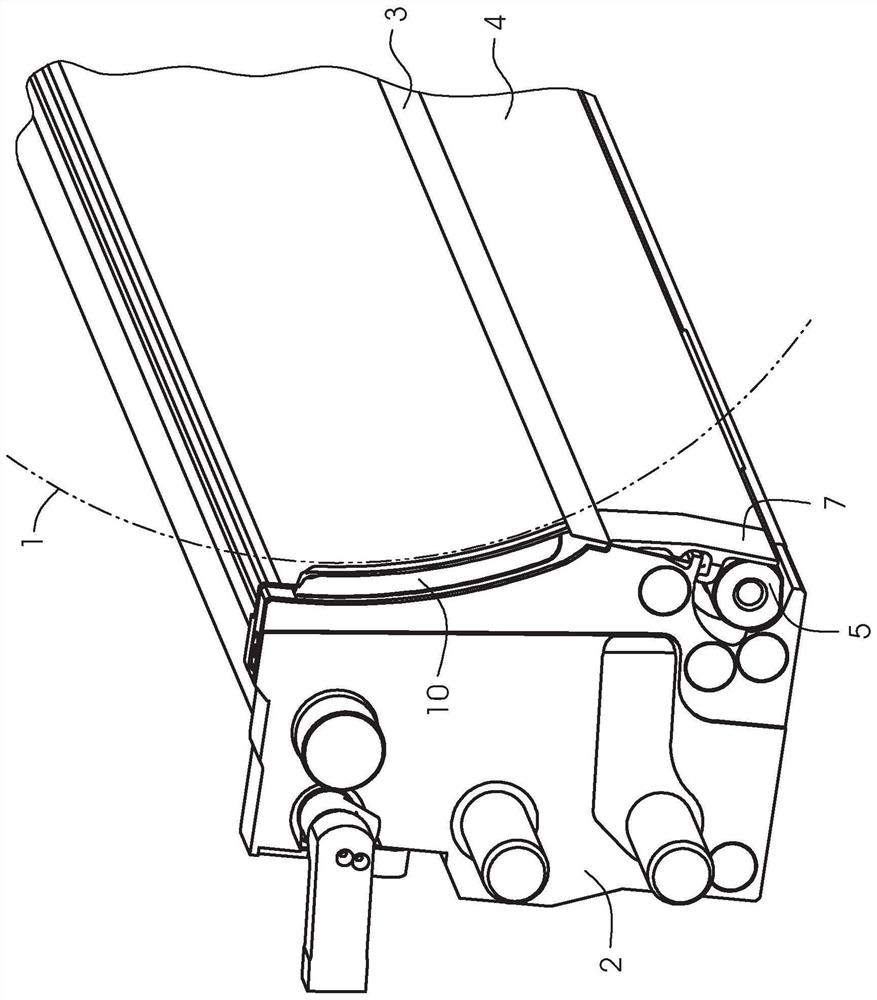
[0016] figure 1 Shows the components of the anilox inking mechanism of a printing press for offset printing. Shown is an anilox roller 1 and an ink fountain 2 with a doctor blade 3 which rests against the anilox roller 1 . The anilox roller 1 is only indicated by phantom lines and only a part of the ink fountain 2 is shown. A clamping strip 4 extends parallel to the scraper 3 for clamping the scraper 3 on the ink fountain. The clamping strip 4 is configured as a rocker and is actuated during clamping by means of an eccentric shaft 5 . One lever arm of the clamping strip 4 bears against the eccentric shaft 5 , while the other lever arm presses against the scraper 3 .
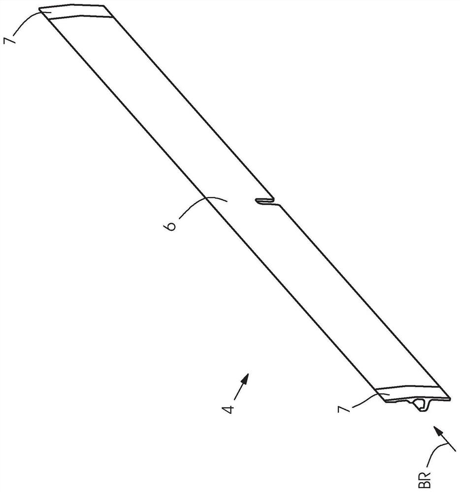
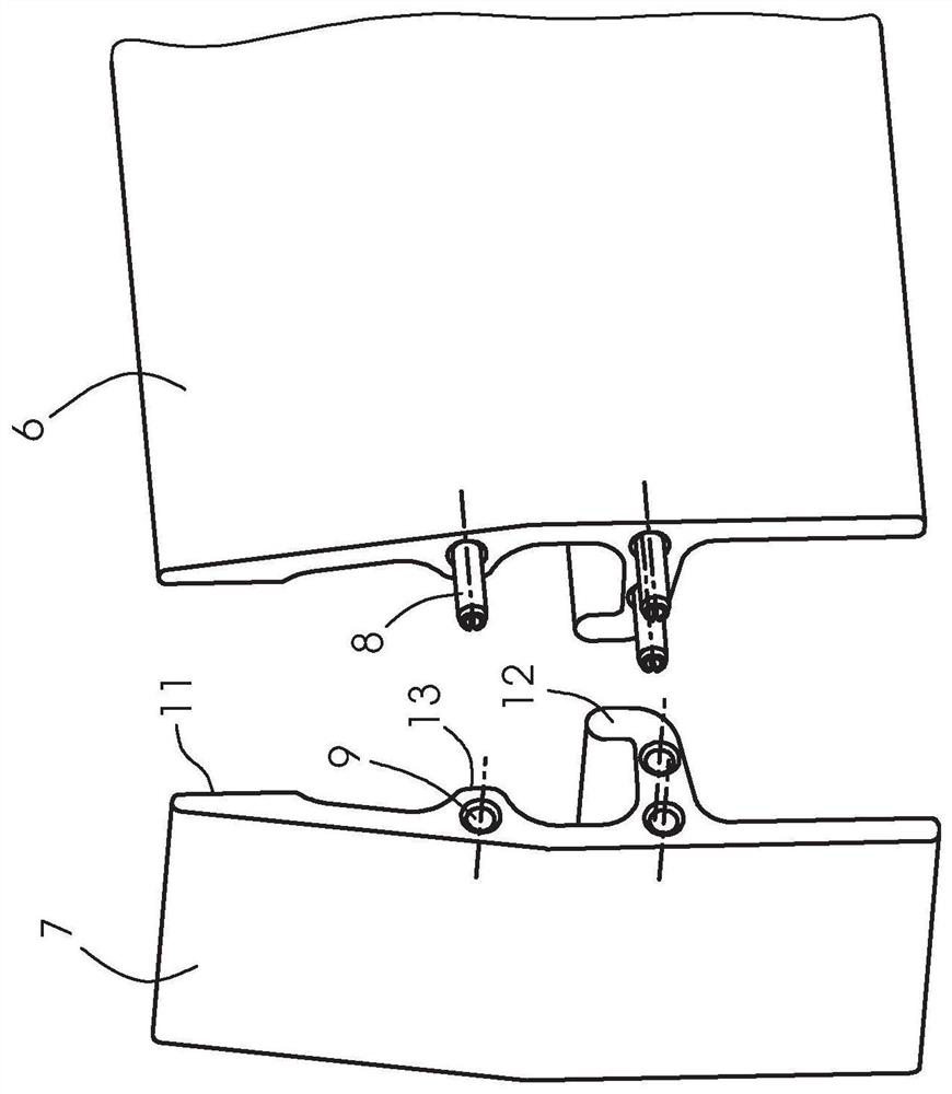
[0017] figure 2 It is shown that the clamping strip 4 comprises two end pieces 7 and a middle piece 6 located between them. The intermediate part 6 is arranged between the two end parts 7 parallel to the axis of rotation of the anilox roll 1 (as viewed according to the viewing direction BR). These end piec...
PUM
 Abstract
Description
Claims
Application Information
 - R&D Engineer
- R&D Manager
- IP Professional
- Industry Leading Data Capabilities
- Powerful AI technology
- Patent DNA Extraction
Browse by: Latest US Patents, China's latest patents, Technical Efficacy Thesaurus, Application Domain, Technology Topic, Popular Technical Reports.
© 2024 PatSnap. All rights reserved.Legal|Privacy policy|Modern Slavery Act Transparency Statement|Sitemap|About US| Contact US: help@patsnap.com