Injection mold

An injection mold and sliding push technology, which is applied in metal processing and other directions, can solve the problems of non-adjustable rotation orientation, high difficulty, and affecting processing efficiency, and achieve the effects of improving processing quality and processing efficiency, reducing operation steps, and simple structure

Inactive Publication Date: 2018-12-11
奉化拓升商贸有限公司
View PDF0 Cites 0 Cited by
  • Summary
  • Abstract
  • Description
  • Claims
  • Application Information

AI Technical Summary

Problems solved by technology

[0002] Cylindrical injection molds are widely used in modern industrial production, but these cylindrical injection molds need to be drilled in the circumferential direction during production, and the rotation orientation of the traditional mold processing device cannot be adjusted after the mold is fixed. It is difficult to punch holes in the circumferential direction of the mold, which seriously affects the processing efficiency

Method used


Image

  • Injection mold
  • Injection mold
  • Injection mold

Examples


Embodiment Construction

[0023] All features disclosed in this specification, or steps in all methods or processes disclosed, may be combined in any manner, except for mutually exclusive features and / or steps.

[0024] Any feature disclosed in this specification (including any appended claims, abstract and drawings), unless expressly stated otherwise, may be replaced by alternative features which are equivalent or serve a similar purpose. That is, unless expressly stated otherwise, each feature is one example only of a series of equivalent or similar features.

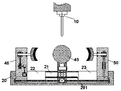
[0025] like Figure 1-6As shown, an injection mold of the device of the present invention includes a drilling head 10 connected to the driving device and a fixing seat 20 arranged below the drilling head 10, and the top end surface of the fixing seat 20 is provided with a Groove 21, the left and right inner walls of the installation groove 21 are respectively provided with a first sliding cavity 22 and a second sliding cavity 23 with an upwar...


PUM


Abstract

The invention discloses an injection mold which includes a drill head which is dynamically connected with a driving device and a fixing seat arranged below the drill head. A mounting groove is formedin the end face of the top of the fixing seat, a first sliding pushing cavity and a second sliding pushing cavity are correspondingly formed in the left and right inner walls of the mounting groove, and the first sliding pushing cavity and the second sliding pushing cavity are provided with upward open ends; a first sliding pushing frame is installed in the first sliding pushing cavity in a sliding pushing mode, a ring turning device is arranged in the first sliding pushing frame, a second sliding pushing frame is installed in the second sliding pushing cavity in a sliding pushing mode, and alocking device is arranged in the second sliding pushing frame; a mounting frame which penetrates through the end face of the top of the fixing seat and extends upward is fixedly arranged in the innerbottom wall of the mounting groove; and a first rotating bin is arranged in the mounting frame in the mounting groove, and a first rotating rod is rotatably installed in the first rotating bin.

Description

technical field [0001] The invention relates to the technical field of mold processing, in particular to an injection mold. Background technique [0002] Cylindrical injection molds are widely used in modern industrial production, but these cylindrical injection molds need to be drilled in the circumferential direction during production, and the rotation orientation of the traditional mold processing device cannot be adjusted after the mold is fixed. It is very difficult to punch holes in the circumferential direction of the mold, which seriously affects the processing efficiency. Contents of the invention [0003] Aiming at the deficiencies of the above-mentioned technologies, the present invention proposes an injection mold. [0004] An injection mold of the device of the present invention comprises a drilling head power-connected with a driving device and a fixing seat arranged below the drilling head, and an installation groove is arranged in the top end surface of ...

Claims


Application Information

Patent Timeline
IPC IPC(8): B26F1/16B26D7/01B26D7/02B26D7/06B26D7/18
CPCB26F1/16B26D7/01B26D7/02B26D7/06B26D7/18
Inventor 毛杰
Owner 奉化拓升商贸有限公司
Why Eureka
Try Eureka