
Metal plate machining feeding device convenient and fast to use

A convenient and sheet metal technology, applied in metal processing equipment, feeding devices, positioning devices, etc., can solve the problems of scratching the operator, not setting up storage space, reducing the time for retrieving materials, etc., and achieve the effect of preventing falling off

Inactive Publication Date: 2018-12-11
合肥全鑫钣金科技有限责任公司
View PDF6 Cites 5 Cited by
  • Summary
  • Abstract
  • Description
  • Claims
  • Application Information

AI Technical Summary

Problems solved by technology

[0002] The first step of sheet metal processing is to load the material. The sheet metal material is large and heavy, and it is troublesome and laborious to load the material, which increases the labor intensity of the operator. Moreover, the edges and corners of the sheet metal material are relatively sharp. It may scratch the operator. In order to make sheet metal feeding more safe and labor-saving, there is currently a convenient feeding device for sheet metal processing, but there are still some things to be improved when using this device; When feeding, when all the sheet metal materials inside the hopper are conveyed to the processing device, the operator cannot be reminded to add materials to the inside of the hopper in time; the inclination angle of the feeding plate is fixed and cannot be disassembled from the hopper, which reduces the The adaptability of the equipment, and it is not reasonable and convenient to use; there is no storage space, and the equipment is often not able to take materials more conveniently when working in some specific areas. feed time

Method used


Image

  • Metal plate machining feeding device convenient and fast to use
  • Metal plate machining feeding device convenient and fast to use
  • Metal plate machining feeding device convenient and fast to use

Examples


Embodiment Construction

[0030] The following will clearly and completely describe the technical solutions in the embodiments of the present invention with reference to the accompanying drawings in the embodiments of the present invention. Obviously, the described embodiments are only some, not all, embodiments of the present invention. Based on the embodiments of the present invention, all other embodiments obtained by persons of ordinary skill in the art without making creative efforts belong to the protection scope of the present invention.

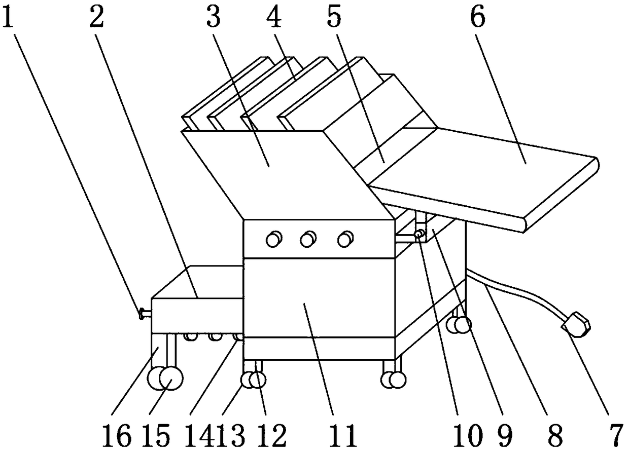
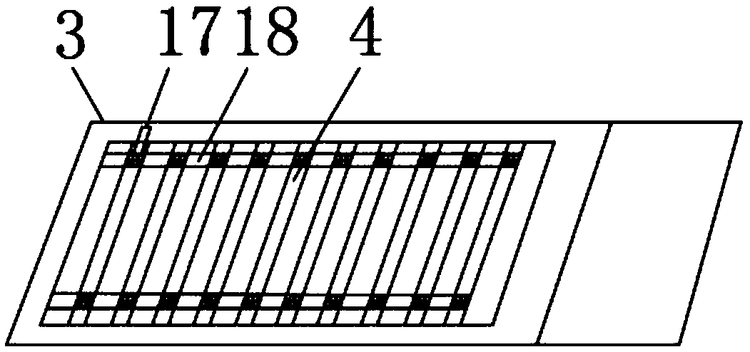
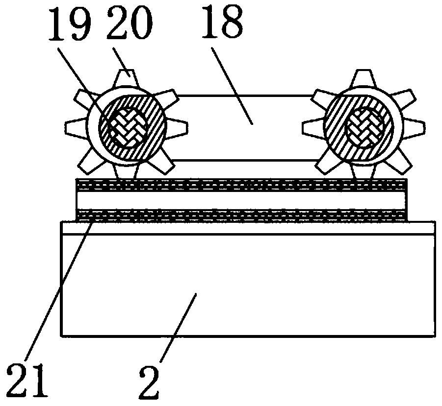
[0031] see Figure 1-6, the present invention provides a technical solution: a convenient feeding device for sheet metal processing, including a feeding box main body 11, a hopper 3 is fixedly installed on the outer surface of the upper end of the feeding box main body 11, and the hopper 3 can continuously provide sheet metal material, the outer surface of one side of the hopper 3 is provided with a discharge port 5, and the inside of the hopper 3 is movably i...


PUM


Abstract

The invention discloses a metal plate machining feeding device convenient and fast to use. The metal plate machining feeding device comprises a feeding box main body. A hopper is fixedly mounted on the outer surface of the upper end of the feeding box body. A discharging opening is formed in the outer surface of one side of the hopper. A conveying belt is movably mounted inside the hopper. Metal plates are movably mounted on the outer surface of the upper end of the conveying belt. Wire pulling posts and a second magnet is fixedly mounted on the outer surface of the one side of the conveying belt. A winding shaft and a first magnet are fixedly mounted on the inner surface of the upper end of the hopper. A wire winding post is movably mounted on the outer surface of the middle of the winingshaft. Hanging grooves are formed inside the discharging opening. A clamping post is movably mounted inside each hanging groove. A hanging rod is movably mounted on the outer surface of the middle ofeach clamping post. By means of the metal plate machining feeding device convenient and fast to use, operators can be reminded of conducting feeding in time, and labor intensity of the operators canbe lowered; equipment suitability can be improved; and metal plate materials can be picked for use conveniently.

Description

technical field [0001] The invention relates to the field of sheet metal processing and feeding, in particular to a convenient feeding device for sheet metal processing. Background technique [0002] The first step of sheet metal processing is to load the material. The sheet metal material is large and heavy, and it is troublesome and laborious to load the material, which increases the labor intensity of the operator. Moreover, the edges and corners of the sheet metal material are relatively sharp. It may scratch the operator. In order to make sheet metal feeding more safe and labor-saving, there is currently a convenient feeding device for sheet metal processing, but there are still some things to be improved when using this device; When feeding, when all the sheet metal materials inside the hopper are conveyed to the processing device, the operator cannot be reminded to add materials to the inside of the hopper in time; the inclination angle of the feeding plate is fixed a...

Claims


Application Information

Patent Timeline
Patent Type & Authority Applications(China)
IPC IPC(8): B21D43/02B21D43/22
CPCB21D43/02B21D43/22
Inventor 范安全
Owner 合肥全鑫钣金科技有限责任公司
Learn More