
High-precision metal pipe bending system and method thereof

A technology of metal pipe fittings and processing systems, applied in metal processing equipment, manufacturing tools, feeding devices, etc., can solve problems such as low bending precision, and achieve high production efficiency, stable production, and high bending precision.

Inactive Publication Date: 2018-12-11
湖州添泽管业有限公司
View PDF7 Cites 6 Cited by
  • Summary
  • Abstract
  • Description
  • Claims
  • Application Information

AI Technical Summary

Problems solved by technology

[0005] The purpose of the present invention is to address the deficiencies of the prior art, to provide a high-precision bending processing system and method for metal pipe fittings, through the cooperation of the pushing component and the positioning mechanism, to realize the automatic preliminary bending of the steel pipe to be bent after the directional transfer , combined with the special structural setting of the placement component and the push component, the feed amount is automatically adjusted during the bending process of the steel pipe, realizing the high-precision bending production of the steel pipe, and solving the technical problem of low bending precision existing in the prior art

Method used


Image

  • High-precision metal pipe bending system and method thereof
  • High-precision metal pipe bending system and method thereof
  • High-precision metal pipe bending system and method thereof

Examples


Embodiment 1

[0040] Embodiments of the present invention are described in detail below, examples of which are shown in the drawings, wherein the same or similar reference numerals designate the same or similar elements or elements having the same or similar functions throughout. The embodiments described below by referring to the figures are exemplary and are intended to explain the present invention and should not be construed as limiting the present invention.

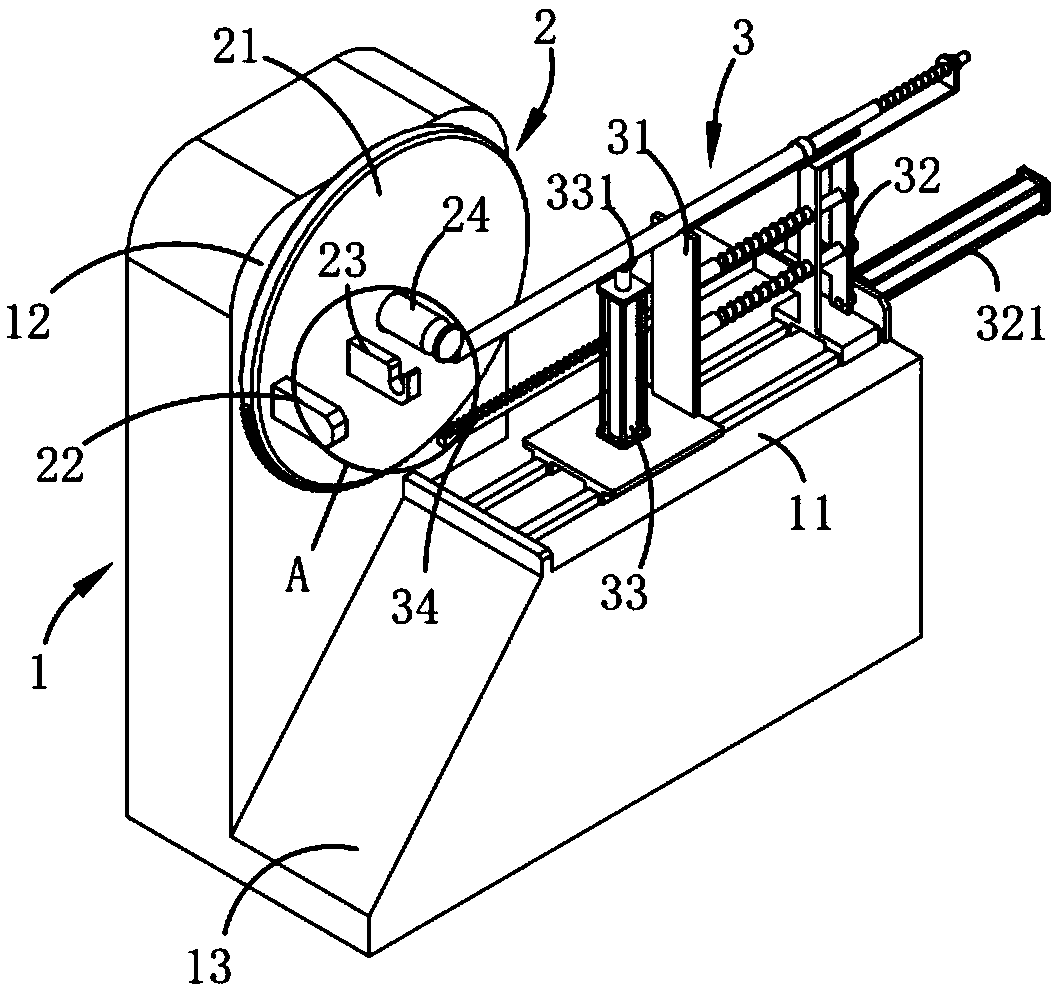
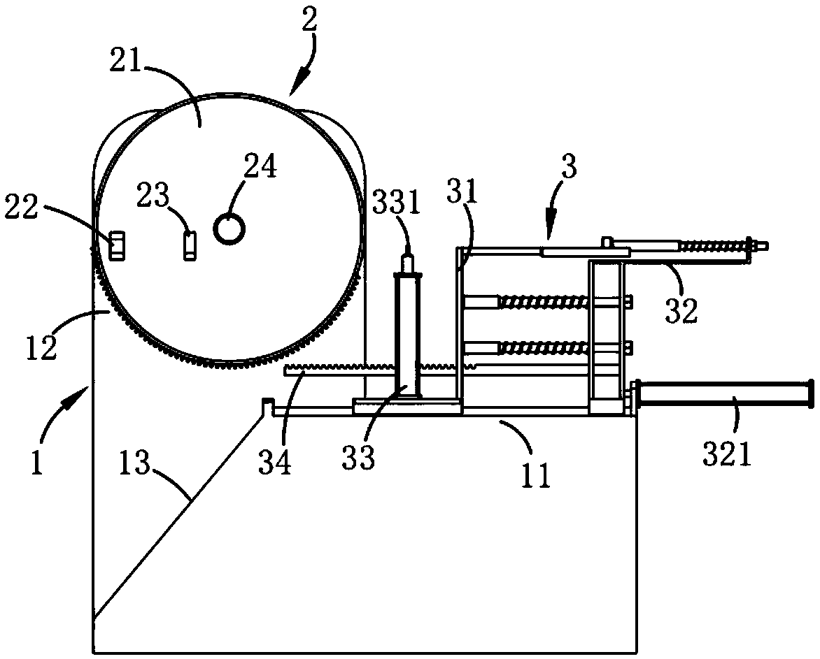
[0041] Such as figure 1 , 2 , 3, 4, 5 and 6, a high-precision bending processing system for metal pipe fittings is characterized in that it includes:

[0042]Frame 1, said frame 1 comprising a horizontal mounting platform 11, a vertical mounting platform 12 and a blanking slide 13 arranged at one end of said horizontal mounting platform 11 and below said vertical mounting platform 12;

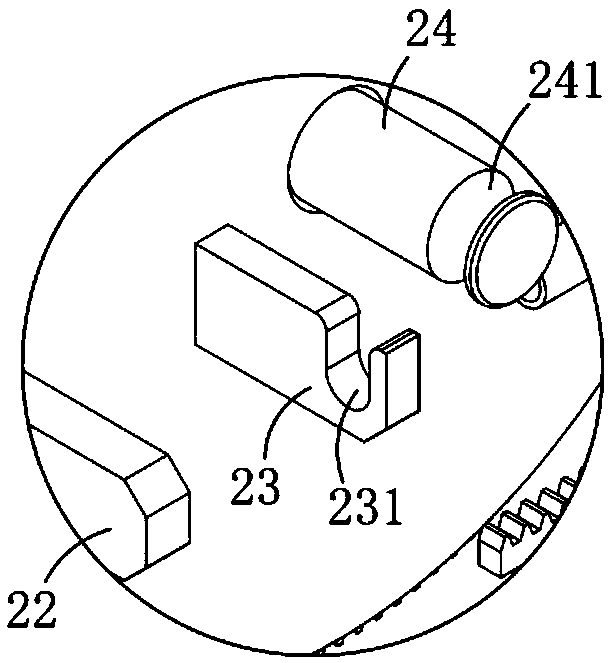
[0043] Positioning mechanism 2, described positioning mechanism 2 is arranged on described vertical mounting platform 12, and it comprises turn...

Embodiment 2

[0050] Among them such as Figure 5 and 7 As shown, the same or corresponding components as in Embodiment 2 use the corresponding reference numerals as in Embodiment 1. For the sake of simplicity, only the differences between Embodiment 2 and Embodiment 2 are described below; the differences between Embodiment 3 and Embodiment 2 The location component 31 also includes a connecting plate 314 connecting the slide table 311 and the placing groove 312, a transmission part 315 arranged on the connecting plate 314 and connected with the support seat 322, the transmission The part 315 includes at least one guide rod 3151 fixedly arranged on the connecting plate 314 along the horizontal direction and a spring 3152 sleeved on the guide rod 3151. The placement assembly 31 is driven to move by the transmission part 315. In this embodiment, there are two transmission parts 315 arranged side by side in the vertical direction. The other end of the guide rod 3151 is limited by a nut, and it...

Embodiment 3

[0055] According to the manual attached Figure 9 A high-precision bending processing method for metal pipe fittings in this embodiment is described.

[0056] A high-precision bending processing method for metal pipe fittings, comprising the following steps:

[0057] (a) For the feeding part, manually place the steel pipe to be bent in the placement groove 312 on the conveying mechanism 3 along its axial direction;

[0058] (b) the pushing part, after the step (a), the push rod 3231 arranged on the support base 322 is driven to move in a reciprocating manner by the driving part 321 on the pushing assembly 32, and the to-be-be placed on the placement groove 312 The bent steel pipe is pushed into the positioning groove 221 on the turntable 21;

[0059] (c) Preliminary bending. After the step (b), the driving part 321 continues to push the support seat 322 to move, and the transmission assembly 34 drives the turntable 21 to rotate in a rack and pinion transmission mode, and coo...


PUM


Abstract

The invention relates to the technical field of metal pipe bending production, in particular to a high-precision metal pipe bending system and a method thereof. The system comprises a frame, a positioning mechanism and a conveying mechanism. The frame comprises a horizontal mounting table, a vertical mounting table and a discharging sliding table; the positioning mechanism comprises a rotating disc, a limiting portion, a supporting portion and a bearing portion; the conveying mechanism comprises a placement component, a pushing component, a bending component and a transmission component, and the transmission component is connected with the pushing component and the rotating disc. A to-be-bent steel pipe in a positioning groove is preliminarily bent through the pushing component which drives the rotating disc to rotate, and the steel pipe is then subjected to secondary bending through the bending component. By cooperation of the pushing component and the positioning mechanism, automaticpreliminary bending of the to-be-bent steel pipe is realized after directional transferring. By special structural setup of the placement component and the pushing component, automatic adjustment offeed amount in a steel pipe bending process is realized, high-precision steel pipe bending is realized, and the technical problem of low bending precision in the prior art is solved.

Description

technical field [0001] The invention relates to the technical field of steel pipe bending production, in particular to a high-precision bending processing system and method for metal pipe fittings. Background technique [0002] At present, steel pipes are widely used in all walks of life, and elbows are mostly used to transport fluids and powdery solids, exchange heat, manufacture cooling and containers, etc., such as the transportation of oil and gas, various cooling and heating pipelines, tap water pipes and Sewage pipes, etc. At present, the bending production of steel pipes is mostly carried out by manual bending, which has high labor intensity and low production efficiency and production quality. [0003] Chinese patent application number: 2016102881493 discloses a high-efficiency bending device for steel pipes, including a bottom plate, cylinder I, electric wheels, pull wires, slide rails, sliders, driven wheels, collection boxes, right frame, top plate, and electric p...

Claims


Application Information

Patent Timeline
Patent Type & Authority Applications(China)
IPC IPC(8): B21D7/024B21D7/025B21D43/00B21D43/02B21D45/02
CPCB21D7/024B21D7/025B21D43/003B21D43/02B21D45/02
Inventor 梅丙林尹勇李威
Owner 湖州添泽管业有限公司
Learn More