


Quick Research
Generate reliable direction feasibility study reports for your R&D in just a few steps.

Technical Q&A
Discover and master advanced knowledge NOW. Basics, ideas, possibilities, all at once.

Find Solutions
As an expert in R&D theories, this can generate solutions to your technical problems instantly.

Evaluate Feasibility
Analyze your overall solution with one click, know your potential R&D risks in advance.

Monitor Landscape
Get weekly tech updates, stay abreast of the latest tech innovations and key insights.
Automatic straightening machine
A straightening machine and automatic technology, applied in metal processing, metal processing equipment, manufacturing tools, etc., can solve the problems of drill pipe straightening not meeting the use requirements, low work efficiency, poor straightening accuracy, etc., and achieve a wide range of applications , Improve the straightening quality, improve the effect of precision
- Summary
- Abstract
- Description
- Claims
- Application Information
AI Technical Summary
Problems solved by technology
Method used
Image

Examples
Embodiment 1
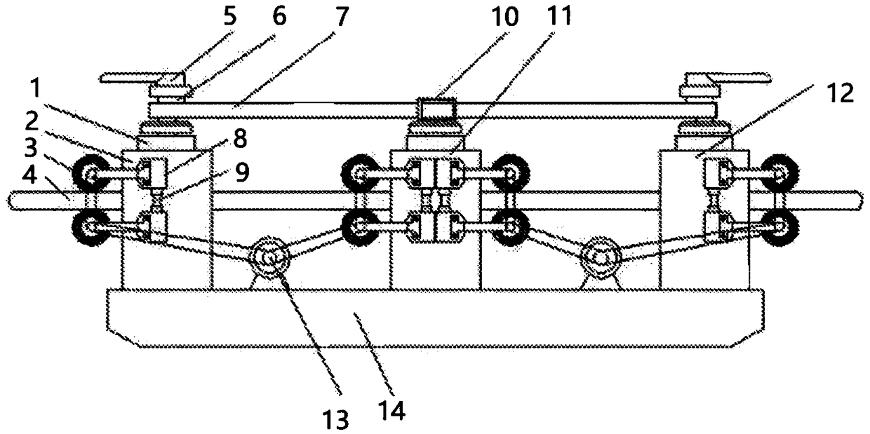
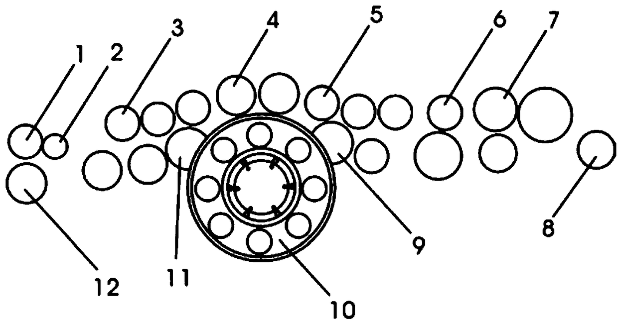
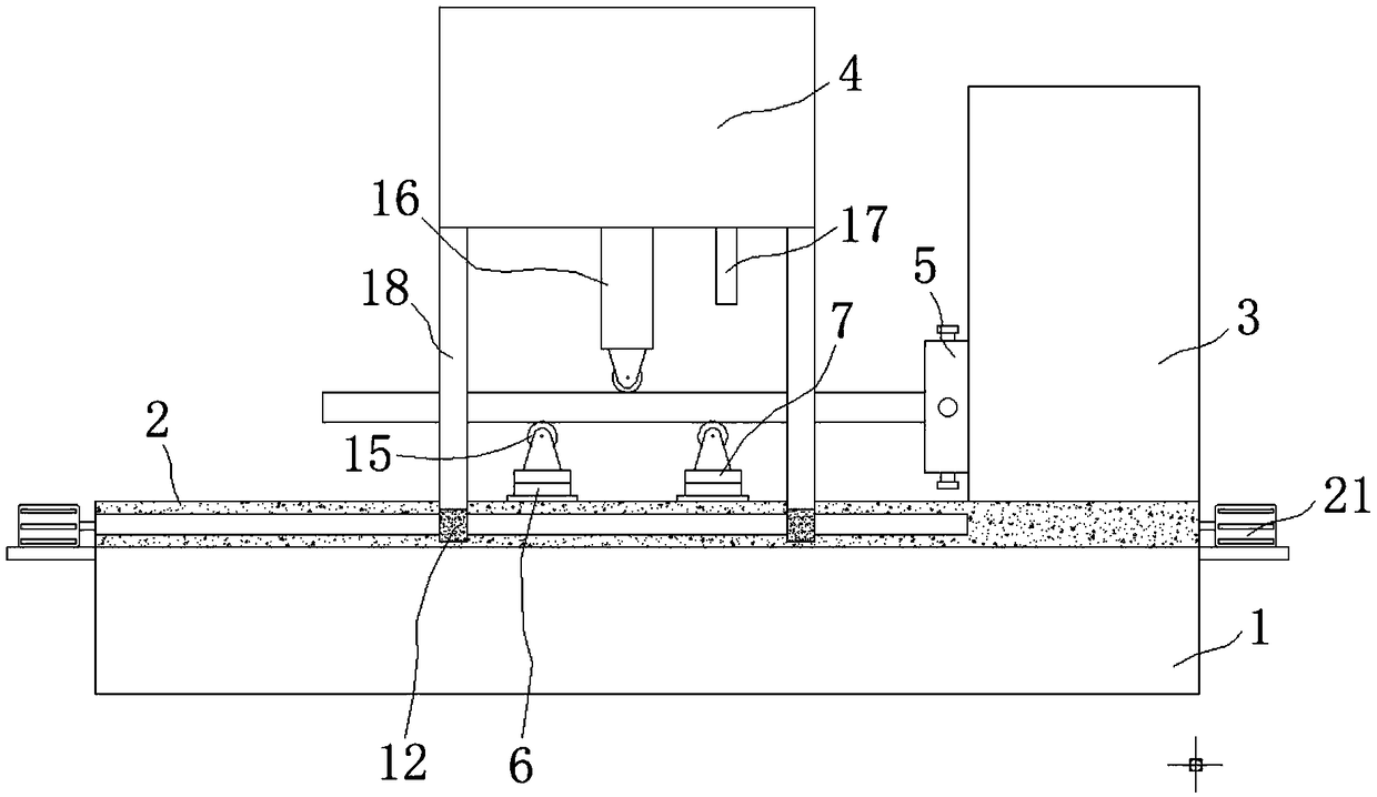
[0052] Such as Figure 3-11 As shown, an automatic straightening machine includes a base 1 and a slide table 2, the slide table 2 is arranged on the upper surface of the base 1, the top side of the slide table 2 is provided with a first box 3, and the first box 3 is provided on the top side of the slide table 2 A first servo motor 20 is arranged inside a box body 3, and the output shaft of the first servo motor 20 is equipped with a turntable 22, and the other end of the turntable 22 is welded with a fixing frame 5, and the first box body 3. A PLC controller 19 is provided at the top of the interior, and a first chute 9 is provided on the other side of the upper surface of the slide table 2, and two sets of first sliders 11 are slidably installed in the first chute 9, and Grooves 13 are provided at the tops of the first sliders 11 of the two groups, and a connection block 6 is provided in the grooves 13, and the connection block 6 is used to connect the cushion block 7 and the...
Embodiment 2
[0069] Such as Figure 3-11 As shown, an automatic straightening machine includes a base 1 and a slide table 2, the slide table 2 is arranged on the upper surface of the base 1, the top side of the slide table 2 is provided with a first box 3, and the first box 3 is provided on the top side of the slide table 2 A first servo motor 20 is arranged inside a box body 3, and the output shaft of the first servo motor 20 is equipped with a turntable 22, and the other end of the turntable 22 is welded with a fixing frame 5, and the first box body 3. A PLC controller 19 is provided at the top of the interior, and a first chute 9 is provided on the other side of the upper surface of the slide table 2, and two sets of first sliders 11 are slidably installed in the first chute 9, and Grooves 13 are provided at the tops of the first sliders 11 of the two groups, and a connection block 6 is provided in the grooves 13, and the connection block 6 is used to connect the cushion block 7 and the...
Embodiment 3
[0081] Such as Figure 3-11 As shown, an automatic straightening machine includes a base 1 and a slide table 2, the slide table 2 is arranged on the upper surface of the base 1, the top side of the slide table 2 is provided with a first box 3, and the first box 3 is provided on the top side of the slide table 2 A first servo motor 20 is arranged inside a box body 3, and the output shaft of the first servo motor 20 is equipped with a turntable 22, and the other end of the turntable 22 is welded with a fixing frame 5, and the first box body 3. A PLC controller 19 is provided at the top of the interior, and a first chute 9 is provided on the other side of the upper surface of the slide table 2, and two sets of first sliders 11 are slidably installed in the first chute 9, and Grooves 13 are provided at the tops of the first sliders 11 of the two groups, and a connection block 6 is provided in the grooves 13, and the connection block 6 is used to connect the cushion block 7 and the...
PUM
| Property | Measurement | Unit |
|---|---|---|
| Surface roughness | aaaaa | aaaaa |
| Straightness | aaaaa | aaaaa |
Abstract
Description
Claims
Application Information
 - R&D Engineer
- R&D Manager
- IP Professional
- Industry Leading Data Capabilities
- Powerful AI technology
- Patent DNA Extraction
Browse by: Latest US Patents, China's latest patents, Technical Efficacy Thesaurus, Application Domain, Technology Topic, Popular Technical Reports.
© 2024 PatSnap. All rights reserved.Legal|Privacy policy|Modern Slavery Act Transparency Statement|Sitemap|About US| Contact US: help@patsnap.com