Computer display brightness controller

A display and controller technology, applied in static indicators, instruments, etc., can solve problems such as troublesome, unclear display, etc., and achieve the effect of convenient use

Inactive Publication Date: 2018-12-07
CHONGQING IND POLYTECHNIC COLLEGE
View PDF8 Cites 0 Cited by
  • Summary
  • Abstract
  • Description
  • Claims
  • Application Information

AI Technical Summary

Problems solved by technology

In the prior art, the display of a computer cannot be seen clearly due to changes in light during use, and it is cumbersome to adjust the brightness of the display according to light changes. Therefore, there is room for improvement

Method used


Image

  • Computer display brightness controller

Examples


Embodiment Construction

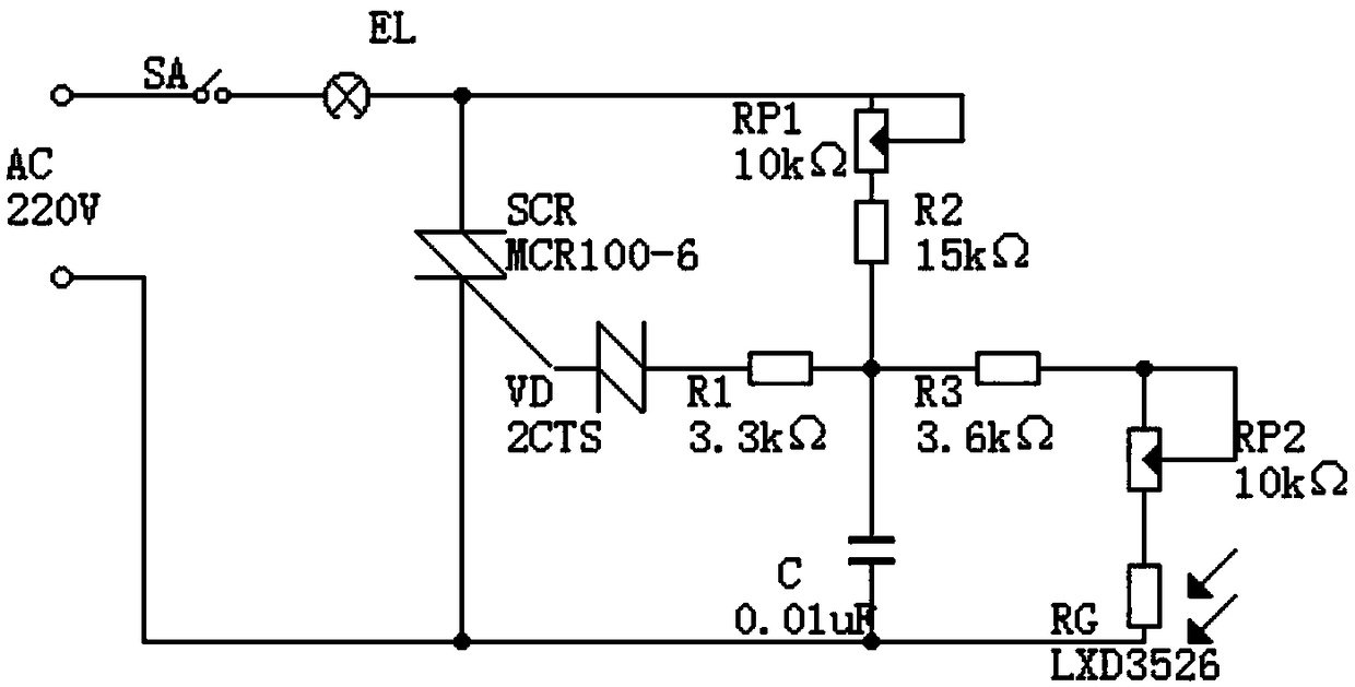
[0010] The present invention will be further described below in conjunction with accompanying drawing:

[0011] like figure 1 Shown: the present invention includes display backlight EL, switch SA, first resistor R1 to third resistor R3, first potentiometer RP1, second potentiometer RP2, triac SCR, bidirectional diode VD, capacitor C and photosensitive Resistor RG, the first end of the switch SA is connected to the first end of the AC power supply AC, the second end of the switch SA is connected to one end of the display backlight EL, and the second end of the display backlight EL At the same time, it is connected with the first end of the bidirectional thyristor SCR, the first end of the first potentiometer RP1 and the sliding end of the first potentiometer RP1, and the other end of the AC power supply AC is simultaneously connected with the second end of the bidirectional thyristor SCR, The first end of the capacitor C is connected to the first end of the photoresistor RG, t...


PUM


Abstract

The invention discloses a computer display brightness controller, which comprises a display backlight lamp, a switch, a first resistor, a second resistor, a third resistor, a first potentiometer, a second potentiometer, a bidirectional silicon controlled rectifier, a bidirectional diode, a capacitor and a photoresistor. Compared with the prior art, the computer display brightness controller can automatically control the brightness of a display according to light changes, can adjust the required brightness by means of the potentiometers as needed, is convenient to use and has the value of popularization and application.

Description

technical field [0001] The invention relates to a computer hardware technology, in particular to a computer display brightness controller. Background technique [0002] A computer, commonly known as a computer, is a modern electronic computing machine used for high-speed computing. It can perform numerical calculations, logical calculations, and has storage and memory functions. It is a modern intelligent electronic device that can run according to the program and process massive data automatically and at high speed. In the prior art, the display of a computer cannot be seen clearly due to light changes during use, and it is cumbersome to adjust the brightness of the display according to light changes. Therefore, there is room for improvement. Contents of the invention [0003] The object of the present invention is to provide a computer display brightness controller in order to solve the above problems. [0004] The present invention achieves the above object through th...

Claims


Application Information

Patent Timeline
Patent Type & Authority Applications(China)
IPC IPC(8): G09G3/34
Inventor 谢雪晴
Owner CHONGQING IND POLYTECHNIC COLLEGE
Why Eureka
Try Eureka