
Application of an acute-corneal wall structure in particle heat transfer

A technology of wall structure and sharp cornea, applied in the field of high-temperature waste heat utilization of granular materials, can solve the problems of air bubbles not easily floating to the middle, large floor space, large power consumption, etc., and achieve high water circulation safety, small floor space, high power low cost effect

Inactive Publication Date: 2020-08-25
NORTH CHINA UNIVERSITY OF SCIENCE AND TECHNOLOGY
View PDF9 Cites 0 Cited by
  • Summary
  • Abstract
  • Description
  • Claims
  • Application Information

AI Technical Summary

Problems solved by technology

[0003] 1) The cooling water is completely penetrated in the water jacket, which cannot form a countercurrent flow with the material, and cannot realize the cascade extraction of waste heat, which seriously restricts the utilization efficiency of waste heat
[0004] 2) The water jacket is spot-welded with two layers of plates. The resistance of the material circulation channel between the two layers of water jacket is too small, the material is close to free fall, the flow rate is too fast, the heat transfer efficiency of the material per unit length of the process is too low, and the metal waste is serious
[0005] 3) The material is close to free fall, the flow rate is too fast, the wear of the particles on the solid surface is serious, and the life of the heat exchanger is short
[0008] 1) The heating surface of this type of heat exchanger is spread horizontally and occupies a large area;
[0009] 2) This type of heat exchanger cannot use the falling trend of material gravity to move the material forward. The power of material movement comes entirely from vibration inertial force, and the power consumption is relatively large.
[0011] 4) When the working medium in the water pipe is a mixture of steam and water, the air bubbles in the water are not easy to float up and tend to the center, but the upper half of the pipe is in the gas phase, and the lower half is in the liquid phase, and the upper half is prone to heat transfer deterioration, causing the pipe to burst

Method used


Image

  • Application of an acute-corneal wall structure in particle heat transfer
  • Application of an acute-corneal wall structure in particle heat transfer

Examples


Embodiment Construction

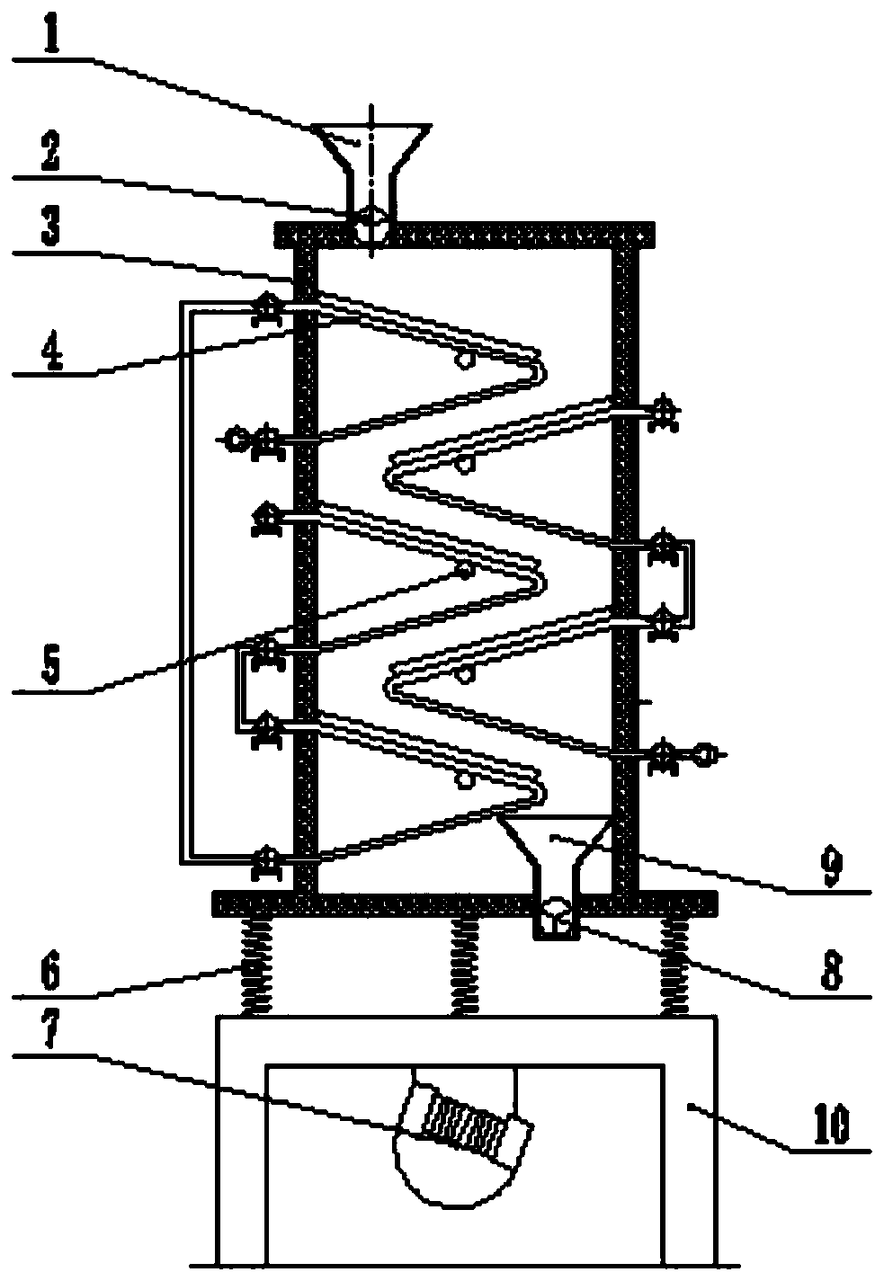
[0032] The application of the acute-corne wall structure of the present invention in particle heat exchange will be described in detail below with reference to the accompanying drawings.

[0033] as attached Figure 1~2 As shown, it includes: a base 10, a furnace body 3 located above the base 10 and a plurality of acute-corneal wall structures 4, the inner wall of the furnace body 3 is filled with heat-insulating materials, and a plurality of Vibrating spring 6 is installed with a vibrating motor 7 on the base 10, which is used to drive the body of heater 3 to vibrate on the vibrating spring 6; the vibrating motor vibrates, and the body of heater vibrates on the vibrating spring with an amplitude of 3-5mm.

[0034] Wherein, a feeding port is formed on the furnace body 3, and a feeding hopper 1 communicates with the feeding port for passing solid particles into the furnace body 3, and a feeding valve 2 is installed on the feeding port.

[0035] Each acute-corner wall structure...


PUM


Abstract

The invention discloses application of acute-angle membrane type wall structures to particle heat exchange. The multiple acute-angle membrane type wall structures are fixedly installed in a furnace body which can vibrate. Each acute-angle membrane type wall structure comprises a plurality of water cooling pipes. The multiple water cooling pipes are arranged at intervals to form water pipe sets, and each water pipe set is bent to form an acute angle. The water pipe sets on the upper clamp faces of the acute angles are arranged in the furnace body in an inclined mode, a connecting fin is connected between every two adjacent water cooling pipes in the inclined water pipe sets in a seamless mode, and a perpendicular fin is fixedly installed at the upper end of each water cooling pipe and is perpendicular to the water cooling pipe. A groove is formed among each connecting fin, the corresponding water cooling pipes located on the two sides of the connecting fin and the two corresponding perpendicular fins. A material rolls to drop, the gravity of the material provides the part of drop power, and the power consumption is low. The mass transfer inside the material is powerful, and the coefficient of heat exchange between the material and the inner wall of the furnace body is high.

Description

technical field [0001] The invention belongs to the technical field of high-temperature waste heat utilization of granular materials, and in particular relates to the application of an acute-corneal wall structure in granular heat exchange. Background technique [0002] The existing direct heat exchange device between powder and solid wall mostly adopts the form of multi-layer water jacket, the inside of the water jacket is filled with cooling water, the water jacket is placed vertically, and the powder is lifted between adjacent water jackets by its own weight. For the downward flow, the water jacket is formed by spot welding of two layers of plates, which is called a water jacketed plate heat exchanger in the industry. The water jacketed plate heat exchanger has the following technical defects: [0003] 1) The cooling water is completely penetrated in the water jacket, which cannot form a counterflow with the material, and cannot realize the cascade extraction of waste he...

Claims


Application Information

Patent Timeline
Patent Type & Authority Patents(China)
IPC IPC(8): F28D11/00F28F1/14F28F9/013
CPCF28D11/00F28F1/14F28F9/013
Inventor 王子兵邢宏伟张玉柱赵涛刘跃
Owner NORTH CHINA UNIVERSITY OF SCIENCE AND TECHNOLOGY
Learn More