
Pull rod structure used for reaction cavity

A technology of reaction chamber and tie rod structure, which is applied in the direction of engine sealing, engine components, mechanical equipment, etc., can solve the problems of tie rod movement sticking, O-ring wear, vibration, etc., achieve good sealing effect, improve yield, Avoid the effect of failure

Active Publication Date: 2018-12-07
48TH RES INST OF CHINA ELECTRONICS TECH GROUP CORP
View PDF7 Cites 1 Cited by
  • Summary
  • Abstract
  • Description
  • Claims
  • Application Information

AI Technical Summary

Problems solved by technology

In this sealing method, on the one hand, the friction between the tie rod and the O-ring during the movement can easily cause the movement of the tie rod to get stuck and vibrate, resulting in the deterioration of the film morphology after epitaxy and the failure of the epitaxy process; on the other hand , after a long time of use, it is easy to wear and age the O-ring and reduce the sealing performance of the O-ring, that is, the sealing of the reaction chamber cannot be guaranteed, which is not good for safety and production process

Method used


Image

  • Pull rod structure used for reaction cavity
  • Pull rod structure used for reaction cavity
  • Pull rod structure used for reaction cavity

Examples


Embodiment Construction

[0023] The present invention will be further described in detail below in conjunction with the accompanying drawings and specific embodiments of horizontal reciprocating motion.

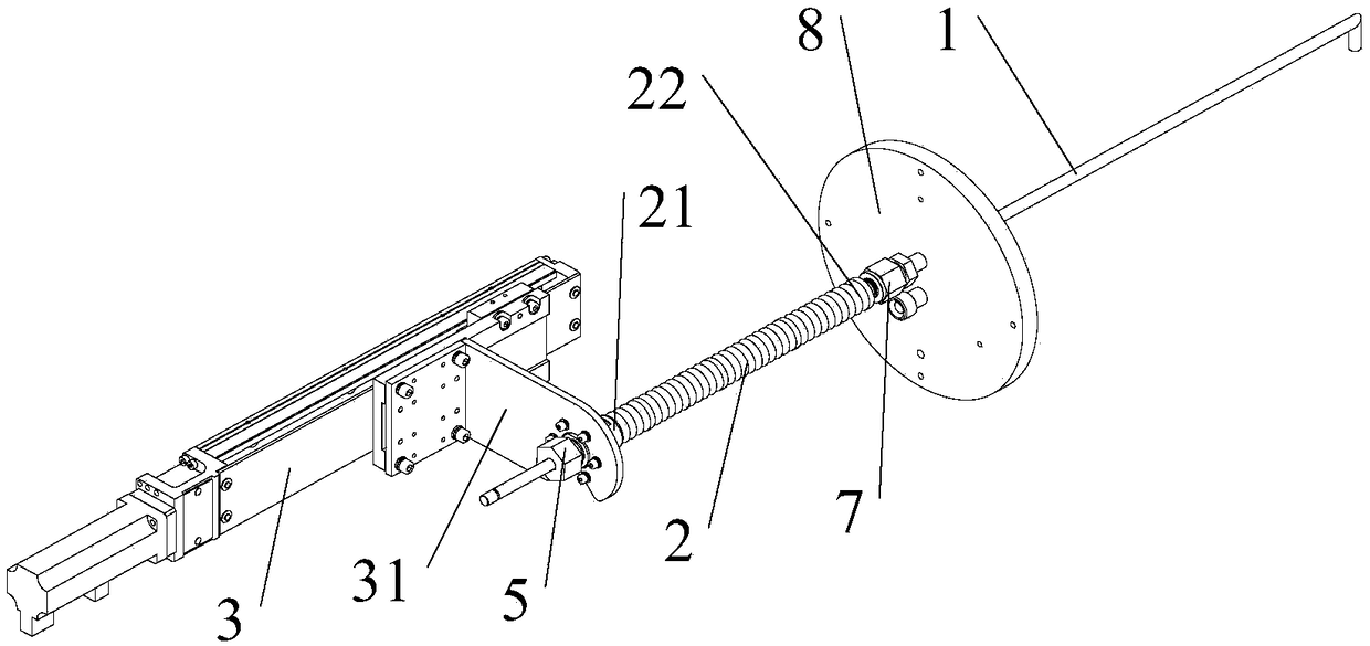
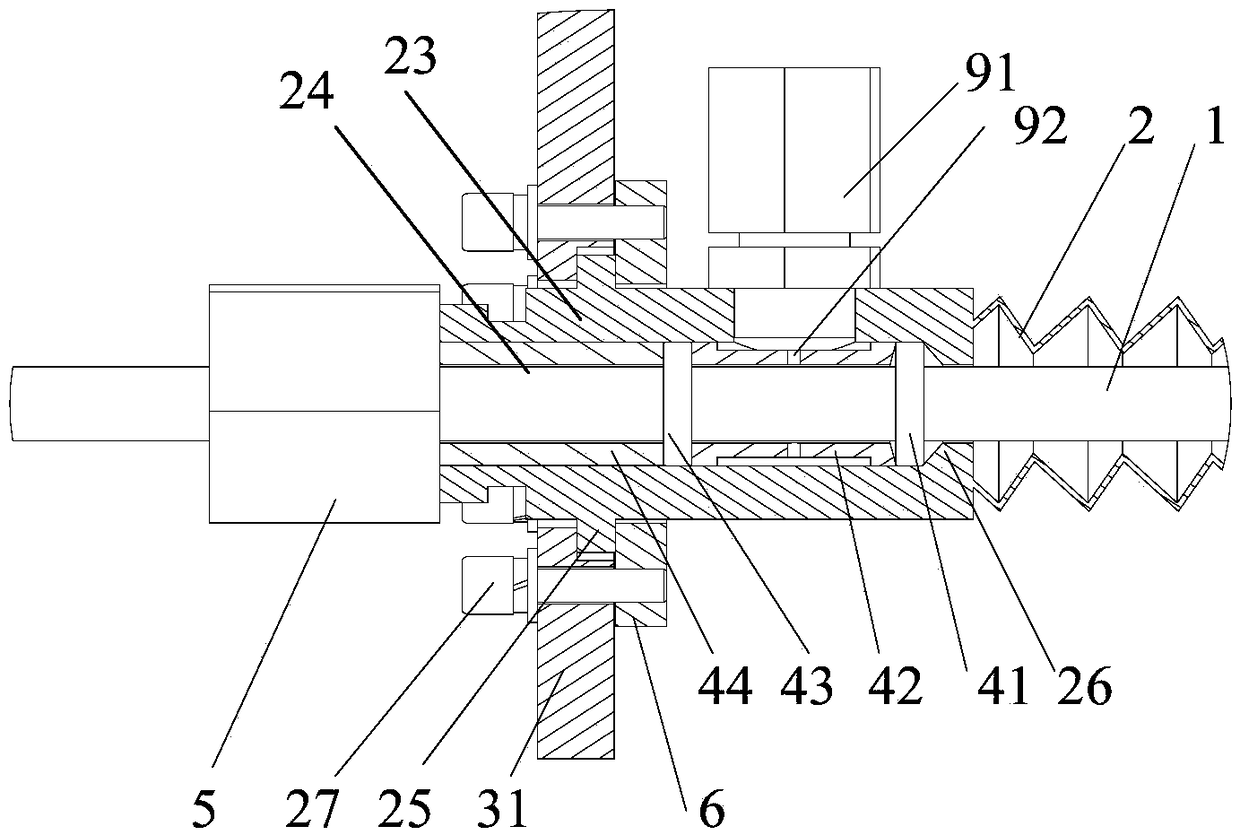
[0024] Such as Figure 1 to Figure 3 As shown, the pull rod structure used in the reaction chamber of this embodiment includes a pull rod 1, a bellows 2 and a drive unit 3. One end of the pull rod 1 is located in the reaction chamber (not shown in the figure), and the other end is located outside the reaction chamber. , the bellows 2 is sleeved on the end of the pull rod 1 outside the reaction chamber, the two ends of the bellows 2 are the first end 21 and the second end 22 respectively, the second end 22 is in sealing connection with the reaction chamber, and the first end 21 has a sealing The sleeve 23 and the sealing sleeve 23 are set on the tie rod 1. An annular sealing cavity 24 is arranged between the sealing sleeve 23 and the pulling rod 1. The first sealing ring 41 and the first sealing press...


PUM


Abstract

The invention discloses a pull rod structure used for a reaction cavity. The pull rod structure comprises a pull rod, a corrugated pipe and a driving unit, one end of the pull rod is located in the reaction cavity, the other end of the pull rod is located outside the reaction cavity, the corrugated pipe is arranged at the end, located outside the reaction cavity, of the pull rod in a sleeving manner, the second end of the corrugated pipe is in sealed connection with the reaction cavity, the first end of the corrugated pipe is provided with a sealing sleeve, the sealing sleeve is arranged on the pull rod in a sleeving manner, and an annular sealing cavity is arranged between the sealing sleeve and the pull rod; the position, located in the annular sealing cavity, on the pull rod is sequentially sleeved with a first sealing ring, a first sealing pressure pad, a second sealing ring and a second sealing pressure pad, the second sealing pressure pad is close to the outer side of the sealingsleeve, and the outer sides of the pull rod and the sealing sleeve are provided with compression pieces used for compressing the second sealing pressure pad; and a driving unit is connected with thesealing sleeve and drives the sealing sleeve to drive the pull rod to do reciprocated linear motion relative to the reaction cavity. According to the pull rod structure, sealing of the pull rod is changed from sliding sealing in the prior art into static sealing of the first sealing ring and the second sealing ring, the sealing effect is good, abrasion to the sealing rings is small, and stabilityand reliability are achieved.

Description

technical field [0001] The invention relates to liquid phase epitaxial growth equipment, in particular to a tie rod structure used in a reaction chamber. Background technique [0002] For liquid phase epitaxial growth equipment, the precise control of the atmosphere, pressure, temperature and other factors in the reaction chamber is the key to ensure the quality of the process. Therefore, higher requirements are put forward for the sealing performance during the movement of the pull rod. The traditional tie rod motion sealing structure adopts sliding seal, which uses a pressing block to compress the O-ring, and the tie rod moves axially relative to the O-ring. In this sealing method, on the one hand, the friction between the tie rod and the O-ring during the movement can easily cause the movement of the tie rod to get stuck and vibrate, resulting in the deterioration of the film morphology after epitaxy and the failure of the epitaxy process; on the other hand , After long...

Claims


Application Information

Patent Timeline
Patent Type & Authority Applications(China)
IPC IPC(8): F16J15/50F16J15/52
CPCF16J15/50F16J15/52
Inventor 魏唯周立庆邸拴虎胡尚正罗才旺杨海燕袁卫华程文进罗臻
Owner 48TH RES INST OF CHINA ELECTRONICS TECH GROUP CORP
Learn More