
Anti-theft lock device

An anti-theft lock and button technology, applied in building locks, door/window accessories, ball handles of wing sashes, etc., can solve problems such as hidden safety hazards, safety accidents, and inability to open the door to enhance ease of use and adaptability Strong, enhance the effect of anti-theft performance

Inactive Publication Date: 2018-12-07
JIANGSU BEITE AUTOMATIC DOOR TECH
View PDF0 Cites 0 Cited by
  • Summary
  • Abstract
  • Description
  • Claims
  • Application Information

AI Technical Summary

Problems solved by technology

This method has two disadvantages: the first is that it is inconvenient to use, and the user has to do two actions to open the door, first press the button and then turn the handle, which is more troublesome than the traditional door opening method; Going out depends on the circuit to control the clutch action, and once a fire occurs or other reasons cause a circuit failure, it will cause people to be unable to open the door and go out from the house, which may easily cause serious safety accidents. This is a very serious design defect.

Method used


Image

  • Anti-theft lock device
  • Anti-theft lock device
  • Anti-theft lock device

Examples


Embodiment Construction

[0019] The present invention can be implemented in the following ways:

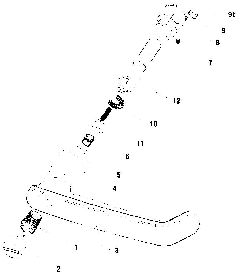
[0020] like figure 1 As shown, the present invention is provided with button return spring 1, button 2, handle body 3, button rivet 4, clutch buffer spring 5, clutch 6, reversing screw 7, handle head 8, positioning block 9, transmission rod return spring 10. Clutch return spring 11 and transmission rod 12. A limiting boss 91 protrudes from the positioning block 9 .

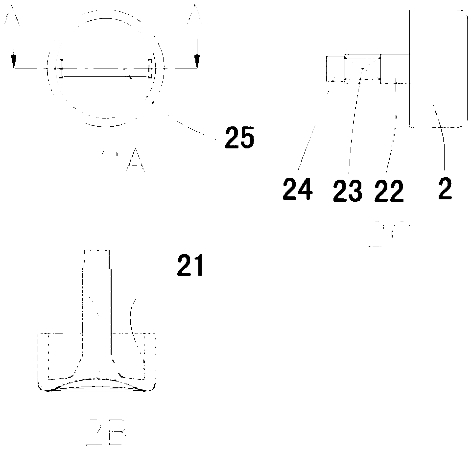
[0021] like figure 2 As shown, the button 2 is provided with an inner cavity 21, a cylindrical platform 22 and a prismatic rod 23 are arranged in the middle of the inner cavity 21, a riveting platform 24 is provided at the front end of the prismatic rod 23, and a rotating groove 25 is provided at the other end of the button 2 .

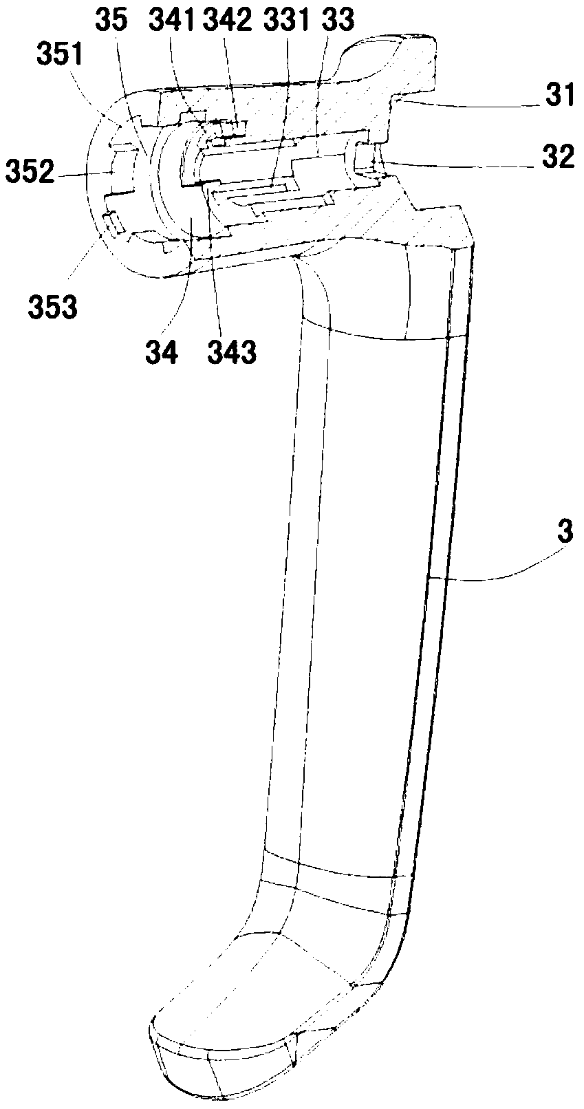
[0022] like image 3 As shown, the front part of the handle body 3 runs through, and a button cavity 31, a button guide diamond hole 32 are arranged in turn, and the other end is provided with a clutch cavity 33...


PUM


Abstract

The invention discloses an anti-theft lock device. The anti-theft function can be reinforced while quick starting is guaranteed. According to the technical scheme, the anti-theft lock device is provided with a button, a button return spring, a handle body, a button riveting piece, a clutch buffer spring, a clutch, a reversing screw, a handle head, a positioning block, a transfer bar return spring,a clutch return spring and a transfer bar. The handle body is provided with a button cavity, a clutch cavity and a handle head cavity. The button is arranged in the button cavity. The clutch is arranged in the clutch cavity. The handle head is arranged in the handle head cavity. The transfer bar penetrates into a handle head hole. The clutch return spring separates the clutch from the transfer bar, so that the handle body idles to achieve the anti-theft function. The button is pressed so that the clutch and the transfer bar can be clamped, and meanwhile the transfer bar and the handle body can rotate synchronously to open a door. The anti-theft lock device is simple and convenient to use, and the anti-theft performance is reliable.

Description

technical field [0001] The invention relates to a handle anti-theft structure of a door lock, in particular to an anti-theft lock device. technical background [0002] At present, the most commonly used mechanical anti-theft door locks are turned with a key outside the door to bring out the dead bolt (anti-theft bolt), and the person inside the door must also use the key to turn and retract the dead bolt to open the door if they want to go out. It cannot be realized to open quickly in an emergency. In order to ensure rapid opening and safe escape in emergency situations, anti-theft locks with escape function are basically used on home anti-theft doors, especially electronic anti-theft locks, which can realize quick locking and quick opening. Quick lock means that the resident lifts the outer handle upwards outside the door after going out, so that the dead tongue of the lock body can be stretched out to lock, and it is not necessary to turn the key counterclockwise to lock ...

Claims


Application Information

Patent Timeline
IPC IPC(8): E05B3/00E05B1/00E05B15/00E05B63/04
CPCE05B3/00E05B1/00E05B15/00E05B63/04
Inventor 史进朱志锋史建刚
Owner JIANGSU BEITE AUTOMATIC DOOR TECH
Learn More