
Steel strand penetrating-binding device

A technology for steel strands and bunching, applied in the field of bunching machines, can solve the problems of inability to install guide caps on the cutting surface of steel strands, slow cutting, hidden dangers, and impact on service life, etc., to improve service life, safety and speed. The effect of cutting and increasing the cutting speed

Active Publication Date: 2018-12-07
云南春鹏钢绞线有限公司
View PDF6 Cites 3 Cited by
  • Summary
  • Abstract
  • Description
  • Claims
  • Application Information

AI Technical Summary

Problems solved by technology

[0006] Aiming at the deficiencies of the prior art, the present invention provides a steel strand threading device, equipped with a separation device, which can quickly and safely cut the steel strand, which solves the problem of slow traditional cutting and potential safety hazards. Cooperating with the movable buckle, the base can be quickly fixed to the scaffold, which improves the convenience of assembly. The guide cap can be installed semi-automatically through the installation device, which solves the problem that the guide cap cannot be conveniently installed on the cut surface of the steel strand, and can reduce the The wear of the wire outlet in the threading of the small steel strand solves the problem that the contact surface between the wire outlet and the steel strand is easy to wear and affects the service life

Method used


Image

  • Steel strand penetrating-binding device
  • Steel strand penetrating-binding device
  • Steel strand penetrating-binding device

Examples


Embodiment Construction

[0030] The following will clearly and completely describe the technical solutions in the embodiments of the present invention with reference to the accompanying drawings in the embodiments of the present invention. Obviously, the described embodiments are only some, not all, embodiments of the present invention. Based on the embodiments of the present invention, all other embodiments obtained by persons of ordinary skill in the art without making creative efforts belong to the protection scope of the present invention.

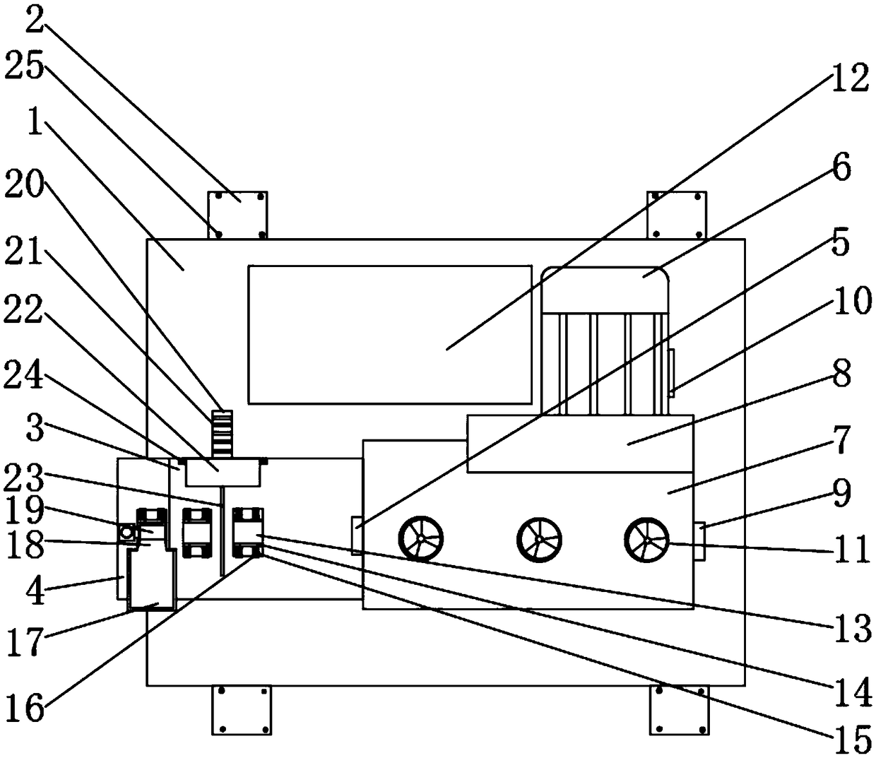
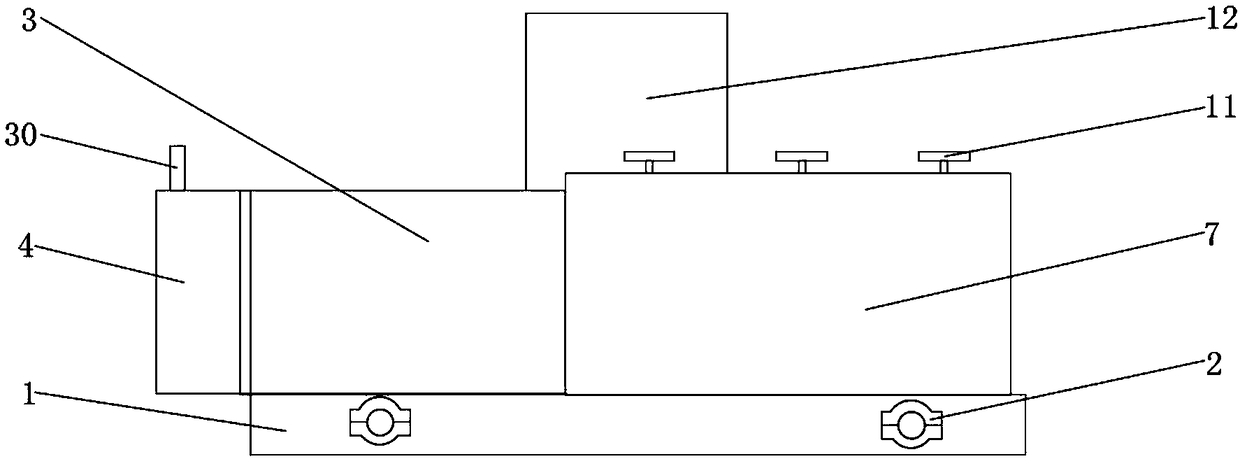
[0031] see Figure 1-6, a steel strand threading device, comprising a base 1, a motor 6 is fixedly installed on the outer surface of the upper end of the base 1, the model of the motor 6 is Y2-132M-4, one end of the motor 6 is provided with a transmission chamber 7, and the motor 6 One side is movably connected with one side of the transmission chamber 7, and the transmission chamber 7 is arranged on the upper outer surface of the base 1, one end of the transm...


PUM


Abstract

The invention relates to the technical field of penetrating-binding machines, and discloses a steel strand penetrating-binding device. The steel strand penetrating-binding device comprises a base, a motor is fixedly installed on the outer surface of the upper end of the base, and a transmission chamber is arranged at one end of the motor and arranged on the outer surface of the upper end of the base. A strand outlet is formed in one end of the transmission chamber, a separating device is arranged on the side, close to the strand outlet, of the transmission chamber, and the separating device isarranged on the outer surface of the upper end of the base. An additionally-installation device is arranged on one side of the separating device and arranged on the outer surface of the upper end ofthe base. Four sets of fixing buckles are arranged on one side of the base. According to the steel strand penetrating-binding device, the steel strand can be cut through the separating device, the base can be fixed with the fixing buckles, the assembly convenience of the steel strand penetrating-binding device is improved, guide caps can be semi-automatically and additionally installed, the abrasion of steel strand to the strand outlet in the penetrating-binding process can be reduced, and the service life of the device is prolonged.

Description

technical field [0001] The invention relates to the technical field of beam threading machines, in particular to a steel strand threading device. Background technique [0002] As market competition becomes more and more fierce, reducing production costs, improving production efficiency, and pursuing profit maximization have become the focus of work for various construction units and enterprises. Now that the country is building large-scale high-speed rail, prefabricated beams are an indispensable process in high-speed rail, and steel strand cutting and threading are the first process in prestressed construction. In the past, manual cutting and threading required at least 5 to 6 people for a 32-meter box girder, and a maximum of 1.5 pieces of box girders were cut and threaded every day. Manual cutting and threading is labor-intensive and requires a lot of labor. At the same time, the efficiency is low, and the next process is often affected because the progress cannot keep u...

Claims


Application Information

Patent Timeline
IPC IPC(8): E01D21/00
CPCE01D21/00
Inventor 边壮伟
Owner 云南春鹏钢绞线有限公司
Learn More