
Novel adjustable turnover lifting appliance

An adjustable and new technology, applied in the direction of load hanging components, hoisting devices, hoisting devices, etc., can solve the problems of workpiece clamping of different sizes, inconvenient adjustment or adjustment performance, inconvenient use of spreaders, etc., to avoid The hanger swings, flips conveniently, and has a good clamping effect

Inactive Publication Date: 2018-12-07
扬州市神力吊具制造有限公司
View PDF0 Cites 15 Cited by
  • Summary
  • Abstract
  • Description
  • Claims
  • Application Information

AI Technical Summary

Problems solved by technology

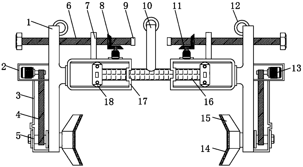
[0003] During the use of the spreader, it is usually necessary to operate different workpieces. Generally, when the spreader operates the workpiece, it is not easy to adjust or the adjustment performance is not perfect. It cannot clamp workpieces of different sizes, and some workpieces need to be flipped. For example, when the workpiece formed in the mold is reversed, it cannot be turned over in all directions, which brings inconvenience to the use of the spreader. At the same time, the stability of the spreader is not high due to the swing of the hook during use. Disadvantages such as prone to accidents

Method used


Image

  • Novel adjustable turnover lifting appliance
  • Novel adjustable turnover lifting appliance
  • Novel adjustable turnover lifting appliance

Examples


Embodiment Construction

[0018] The following will clearly and completely describe the technical solutions in the embodiments of the present invention with reference to the accompanying drawings in the embodiments of the present invention. Obviously, the described embodiments are only some, not all, embodiments of the present invention. Based on the embodiments of the present invention, all other embodiments obtained by persons of ordinary skill in the art without making creative efforts belong to the protection scope of the present invention.

[0019] In the description of the present invention, it should be noted that the terms "center", "upper", "lower", "left", "right", "vertical", "horizontal", "inner", "outer" etc. The indicated orientation or positional relationship is based on the orientation or positional relationship shown in the drawings, and is only for the convenience of describing the present invention and simplifying the description, rather than indicating or implying that the referred d...


PUM


Abstract

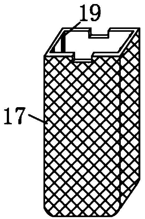
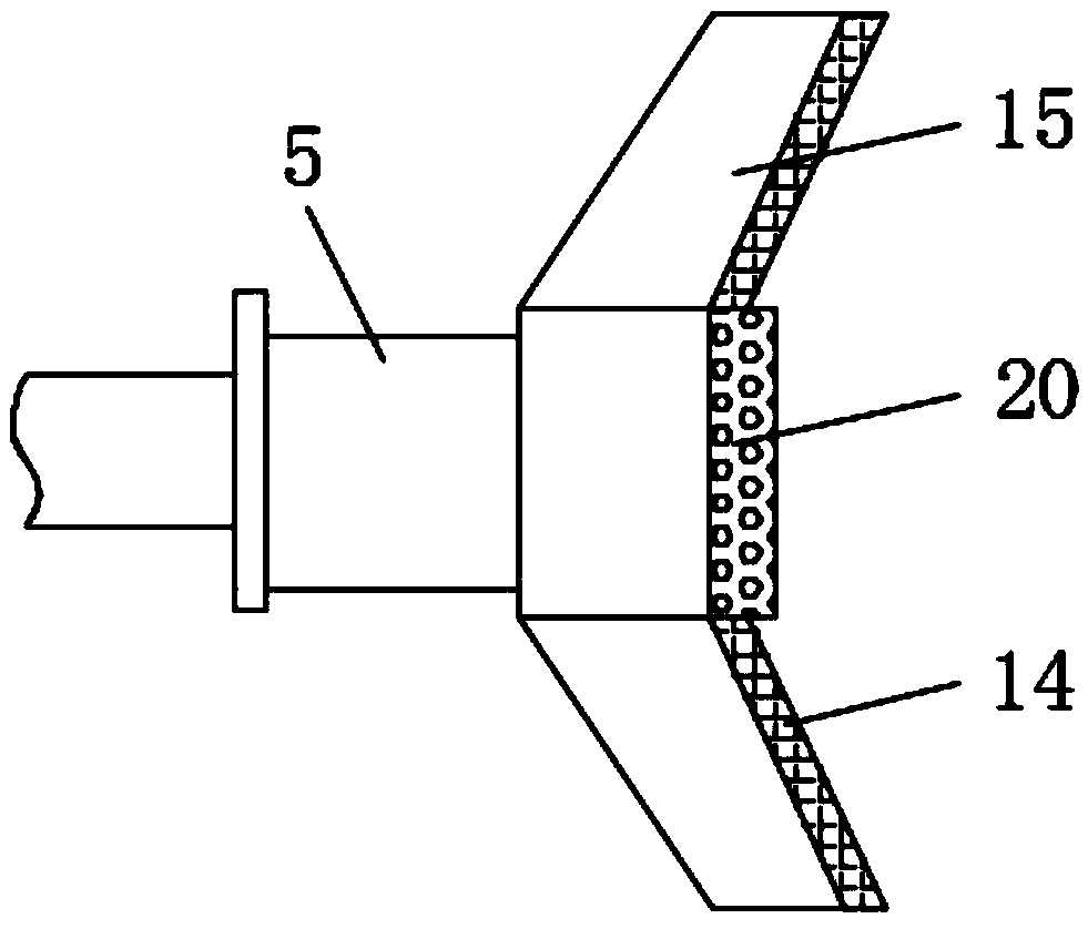
The invention discloses a novel adjustable turnover lifting appliance comprising suspension frames and a bearing plate. Screw rods are connected to one sides of the tops of the suspension frames through screw holes. A fixing plate is connected to the surface of one side of each screw rod in a threaded mode. A bevel gear is arranged on one side of each fixing plate and located on the surface of thecorresponding screw rod. One side of each bevel gear is engaged with a first motor. A sleeve is welded to the position, on the inner side wall of the corresponding suspension frame, of the bottom ofeach first motor. According to the novel adjustable turnover lifting appliance, an adjusting mechanism composed of the suspension frames, the screw rods, the fixing plates, the bearing plate, a hanger, the sleeves and the first motors is adopted, when adjustment is needed, by operating the two symmetrically-arranged first motors and the bevel gears on the surfaces of the two screw rods to make engaged rotation, the fixing plates connected to the surfaces of one sides of the screw rods can drive the sleeves to move, meanwhile, the interiors of the two sleeves are in sliding connection with thebearing plate through rollers, accordingly, the suspension frames can be widened to a certain extent so as to lift workpieces of different sizes conveniently, and thus adjustability of the novel adjustable turnover lifting appliance is improved.

Description

technical field [0001] The invention relates to the technical field of hoisting tools, in particular to a novel adjustable turning hoist. Background technique [0002] Special rigging such as hooks, wire ropes, and chains are commonly used in the spreader. Lifting suction cups, clamps and forks can be used as special spreaders on the crane for a long time, and can also be used as replaceable auxiliary spreaders hanging on the hook for temporary use. They are often used in multi-cargo warehouses and yards to improve work efficiency. The spreader for grabbing bulk materials is generally a grab bucket with a jaw plate that can be opened and closed, and an electromagnetic chuck can also be used to absorb magnetic materials such as metal chips. Commonly used spreaders for lifting fluid materials are buckets and hanging tanks. Generally, molten steel or chemical solutions are discharged by tilting or bottom plugging, and fluid materials such as concrete are discharged by opening...

Claims


Application Information

Patent Timeline
Patent Type & Authority Applications(China)
IPC IPC(8): B66C1/44B66F19/00
CPCB66C1/44B66F19/00
Inventor 高进贤费远林高天文
Owner 扬州市神力吊具制造有限公司
Learn More