


Quick Research
Generate reliable direction feasibility study reports for your R&D in just a few steps.

Technical Q&A
Discover and master advanced knowledge NOW. Basics, ideas, possibilities, all at once.

Find Solutions
As an expert in R&D theories, this can generate solutions to your technical problems instantly.

Evaluate Feasibility
Analyze your overall solution with one click, know your potential R&D risks in advance.

Monitor Landscape
Get weekly tech updates, stay abreast of the latest tech innovations and key insights.
Printing device applied to drying agent box in medicine bottle
A technology of printing device and desiccant, applied in printing, typewriter and other directions, can solve problems such as unfavorable production cost, waste of oil material, reduction, etc., and achieve the effect of saving oil material and slowing down the falling speed.
- Summary
- Abstract
- Description
- Claims
- Application Information
AI Technical Summary
Problems solved by technology
Method used
Image

Examples
Embodiment 1
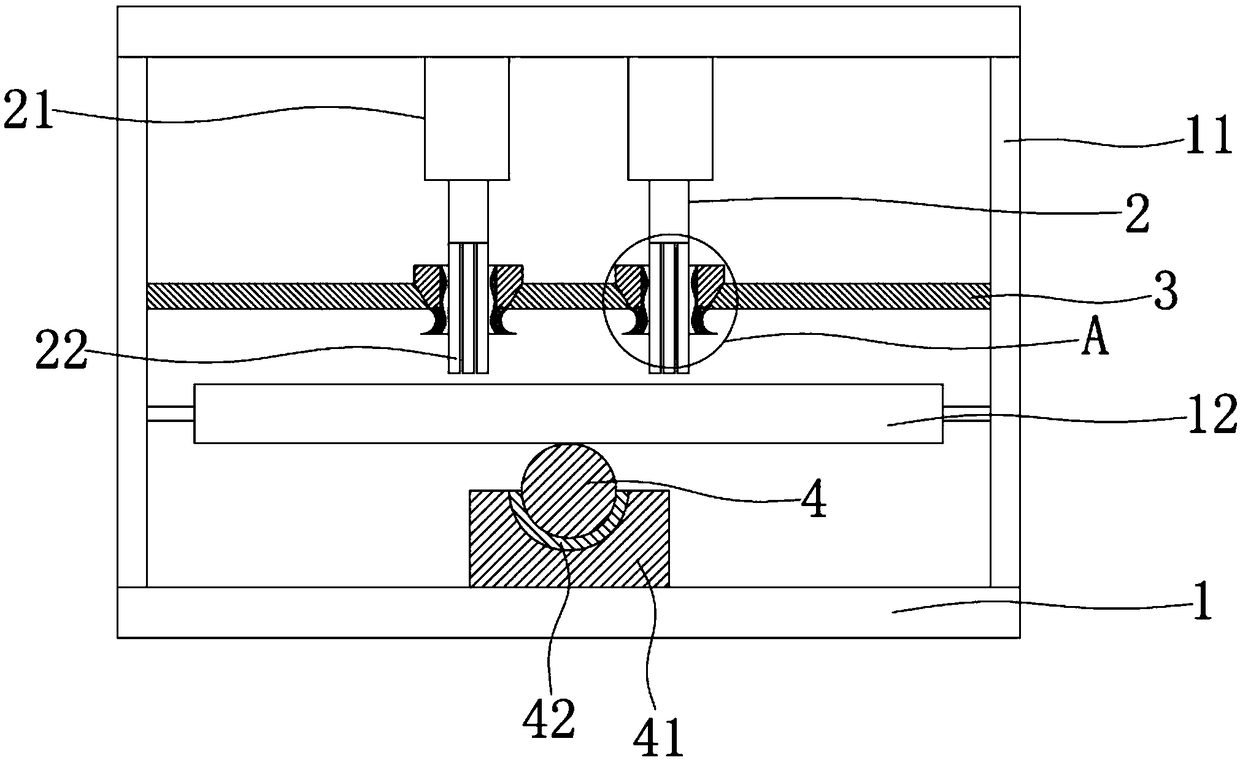
[0019] see Figure 1 to Figure 2 , the figure shows a printing device applied to a desiccant box in a medicine bottle provided by Embodiment 1 of the present invention, which includes a base 1, a frame 11 is fixedly arranged on the base 1, and a frame 11 is provided with Horizontally movable printing table 12, a plurality of printing molds 2 are arranged above the printing table 12, the printing molds 2 are connected with lifting drive parts 21, and the lifting driving parts 21 are fixedly installed on the top of the frame 11, and the ends of the printing molds 2 have Brush head 22, the plate body 3 that horizontal setting is fixedly installed on the frame 11, plate body 3 is positioned at the top of printing table 12, is provided with the through hole 31 that passes for brush head 22 on the plate body 3, the hole wall of through hole 31 A wave-shaped guide surface 32 is provided on the top.
[0020] The printing device applied to the desiccant box in the medicine bottle prov...
Embodiment 2
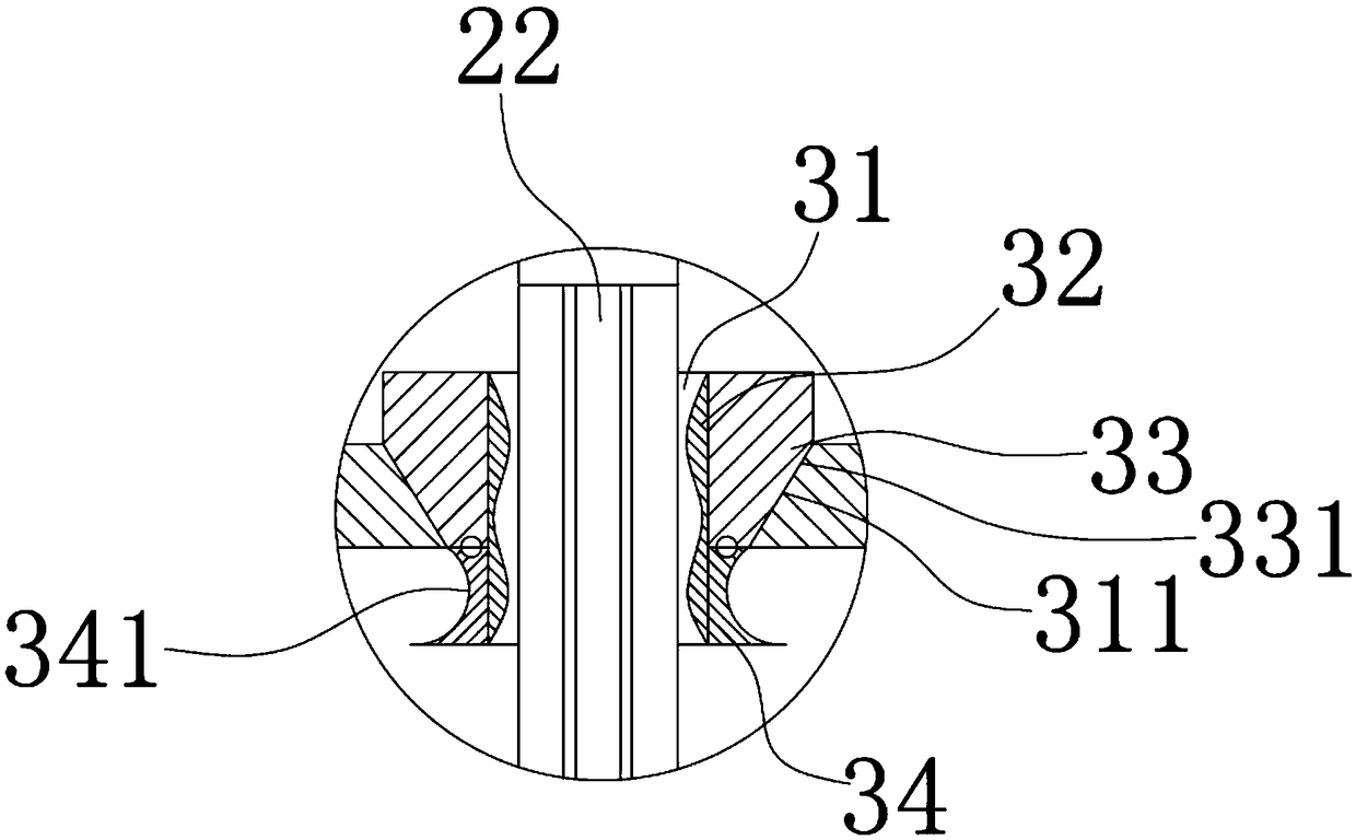
[0022] see Figure 1 to Figure 2 , the figure shows a self-locking slider device applied to injection molds provided by Embodiment 2 of the present invention. This embodiment further makes the following technical solutions as improvements on the basis of the above embodiments: A slope surface 311 is provided on the hole wall of the hole 31; a first guide block 33 is installed on the slope surface 311, and a chamfer surface 331 connected and matched with the slope surface 311 is provided on the first guide block 33; The bottom is hinged with a second guide block 34, and the guide surface 32 is connected to the surfaces of the first guide block 33 and the second guide block 34; the back side of the second guide block 34 is provided with an arc-shaped groove 341; the guide surface 32 is a rubber pad. Through the setting of the above structure, the installation of the guide surface can be made more stable, and the hinged structure of the second guide surface can form the width sel...
Embodiment 3
[0024] see Figure 1 to Figure 2 , the figure shows a self-locking slider device applied to injection molds provided by Embodiment 3 of the present invention. This embodiment further makes the following technical solutions as improvements on the basis of the above embodiments: machine A movable roller body 4 is arranged on the seat 1, and the printing table 12 is located above the roller body 4; the roller body 4 is installed in the roller body seat 41, and a soft gasket 42 is arranged in the roller body seat 41, which can be specifically rubber As for the gasket, the roller body 4 is rotatably installed in the soft gasket 42 . Through the arrangement of the above structure, the printing table can be kept level and form a buffering effect during printing.
PUM
 Abstract
Description
Claims
Application Information
 - R&D Engineer
- R&D Manager
- IP Professional
- Industry Leading Data Capabilities
- Powerful AI technology
- Patent DNA Extraction
Browse by: Latest US Patents, China's latest patents, Technical Efficacy Thesaurus, Application Domain, Technology Topic, Popular Technical Reports.
© 2024 PatSnap. All rights reserved.Legal|Privacy policy|Modern Slavery Act Transparency Statement|Sitemap|About US| Contact US: help@patsnap.com