
Grinding wheel improving grinding cooling and grinding quality

A grinding wheel and grinding technology, applied in the direction of bonded grinding wheels, abrasives, metal processing equipment, etc., can solve the problems such as the inability to dissipate the grinding heat in time, the short dressing interval of the grinding wheel, and the reduction of grinding efficiency, and achieve good centrifugal throwing effect. , Reduce grinding scratches and improve the effect of grinding surface quality

Inactive Publication Date: 2018-12-07
江苏三锐研磨科技有限公司
View PDF0 Cites 0 Cited by
  • Summary
  • Abstract
  • Description
  • Claims
  • Application Information

AI Technical Summary

Problems solved by technology

[0002] The grinding wheel generates a lot of grinding heat during the grinding process. Now the grinding heat generated by the grinding wheel during the grinding process cannot be dissipated in time, resulting in the following defects: first, it is easy to produce grinding burns, and the service life is short; second, the grinding debris The grinding wheel cannot be effectively brought out, and it is easy to cause grinding scratches, resulting in poor grinding quality; third, the dressing interval of the grinding wheel is short, which reduces the grinding efficiency

Method used


Image

  • Grinding wheel improving grinding cooling and grinding quality
  • Grinding wheel improving grinding cooling and grinding quality
  • Grinding wheel improving grinding cooling and grinding quality

Examples


Embodiment 1

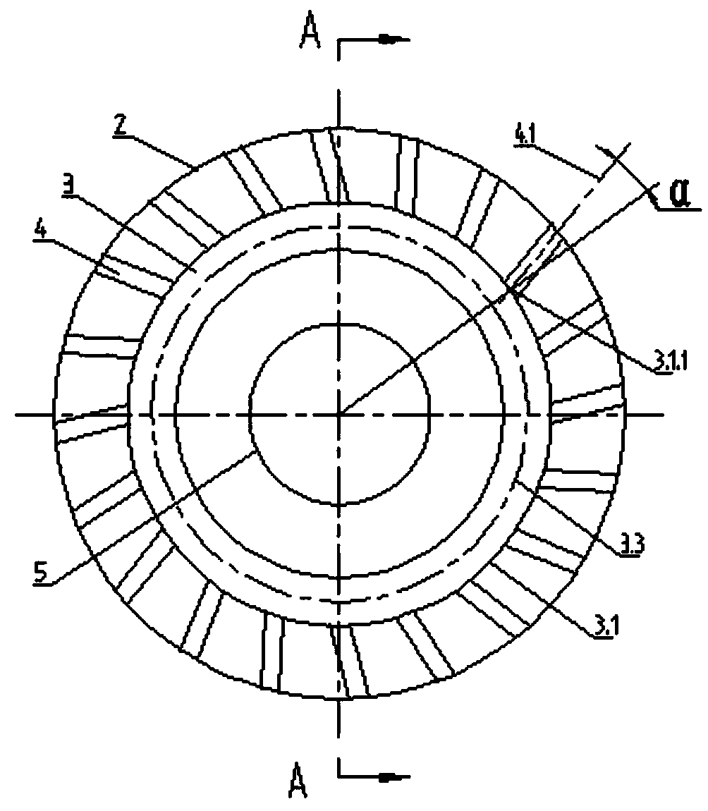
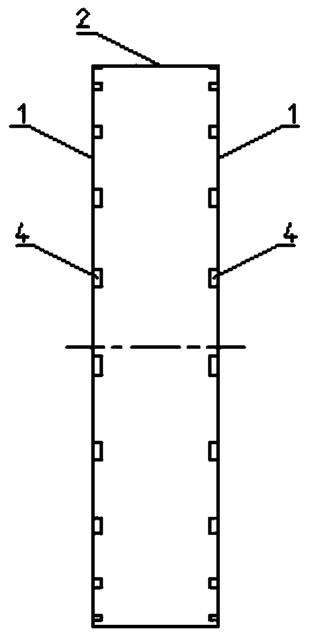
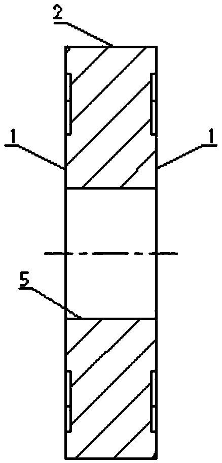
[0018] The grinding wheel shown in the accompanying drawings to improve the heat dissipation of grinding and improve the grinding quality is a grinding wheel with a thickness ≥ 20 mm and a grinding wheel diameter greater than 200 mm but not greater than 500 mm. The two ends 1 of the grinding wheel are respectively provided with a center of the outer circular surface 2 of the grinding wheel. An annular groove 3 with coaxial axes, the diameter of the central axis 3.3 of the annular groove 3 is half of the sum of the diameter of the outer circular surface 2 and the inner hole 5 of the grinding wheel, the width of the annular groove 3 is 5mm, and the depth is 1mm .

[0019] On the circumference between the annular groove 3 of each end face 1 of the described grinding wheel and the outer circular surface 2, there are 20 straight grooves 4 that are evenly distributed, eccentric, and communicate with the annular groove 3 and the outer circular surface 2 (in other embodiments , can be...

Embodiment 2

[0021] The grinding wheel shown in the accompanying drawings to improve the heat dissipation of grinding and improve the grinding quality is a grinding wheel with a thickness ≥ 20 mm and a grinding wheel diameter greater than 200 mm but not greater than 500 mm. The two ends 1 of the grinding wheel are respectively provided with a center of the outer circular surface 2 of the grinding wheel. An annular groove 3 with coaxial axes, the diameter of the central axis 3.3 of the annular groove 3 is 1 / 3 of the sum of the diameter of the outer circular surface 2 of the grinding wheel and the diameter of the inner hole 5, the width of the annular groove 3 is 10 mm, and the depth is 2mm.

[0022] On the circumference between the annular groove 3 of each end face 1 of the described grinding wheel and the outer circular surface 2, there are 20 straight grooves 4 that are evenly distributed, eccentric, and communicate with the annular groove 3 and the outer circular surface 2 (in other embod...

Embodiment 3

[0024] The grinding wheel shown in the accompanying drawings to improve the heat dissipation of grinding and improve the grinding quality is a grinding wheel with a thickness ≥ 20 mm and a grinding wheel diameter greater than 500 mm but not greater than 600 mm. The two ends 1 of the grinding wheel are respectively provided with a center of the outer circular surface 2 of the grinding wheel. An annular groove 3 with coaxial axes, the diameter of the central axis 3.3 of the annular groove 3 is 2 / 3 of the sum of the diameter of the outer circular surface 2 of the grinding wheel and the diameter of the inner hole 5, the width of the annular groove 3 is 15mm, and the depth is 2mm.

[0025] On the circumference between the annular groove 3 of each end face 1 of the described grinding wheel and the outer circular surface 2, there are 20 straight grooves 4 that are evenly distributed, eccentric, and communicate with the annular groove 3 and the outer circular surface 2 (in other embodi...


PUM


Abstract

The invention discloses a grinding wheel improving grinding cooling and grinding quality. The thickness of the grinding wheel is larger than or equal to 20 mm. The two end faces of the grinding wheelare each provided with an annular groove. When the diameter of the grinding wheel is larger than 200 mm and smaller than or equal to 500 mm, is larger than 500 mm and smaller than or equal to 600 mm,and is larger than 600 mm, the thickness of the annular grooves is 5-10 mm, 15-20 mm and 25-40 mm correspondingly, and the depth of the annular grooves is 1-2 mm, 2-3 mm and 2-3 mm correspondingly. The circumference between the annular groove in each end face of the grinding wheel and the outer circle surface is provided with a plurality of evenly distributed and eccentric straight grooves which achieving communication of the corresponding annular groove and the outer circle surface, the width of the straight grooves is 2-4 mm, and the depth of the straight grooves is the same as that of the annular grooves. On the end faces of the grinding wheel, the included angle alpha between the connection line of the intersection point of the center axis of the straight grooves and the outside grooveedges of the annular grooves and the center of the grinding wheel, and the center axis of the straight grooves is 10-20 degrees, when the diameter of the grinding wheel is larger than 200 mm and smaller than or equal to 500 mm, is larger than 500 mm and smaller than or equal to 600 mm, and is larger than 600 mm, the included angles of center lines of adjacent straight grooves are 18 degrees, 7.5degrees and 6 degrees correspondingly. According to the grinding wheel, grinding cooling is significantly improved, service life is significantly prolonged, and grinding quality is improved.

Description

technical field [0001] The invention relates to a precision grinding tool, in particular, the invention relates to a grinding wheel for grinding. Background technique [0002] The grinding wheel generates a lot of grinding heat during the grinding process. Now the grinding heat generated by the grinding wheel during the grinding process cannot be dissipated in time, resulting in the following defects: first, it is easy to produce grinding burns, and the service life is short; second, the grinding debris If the grinding wheel cannot be effectively brought out, it is easy to cause grinding scratches, resulting in poor grinding quality; the third is that the dressing interval of the grinding wheel is short, which reduces the grinding efficiency. Contents of the invention [0003] Aiming at the deficiencies of the prior art, the invention provides a grinding wheel which significantly improves the heat dissipation of grinding, prolongs the service life and improves the grinding...

Claims


Application Information

Patent Timeline
Patent Type & Authority Applications(China)
IPC IPC(8): B24D5/10
CPCB24D5/10
Inventor 马骏峰钱勇军申翔马嘉琪
Owner 江苏三锐研磨科技有限公司
Learn More