
3D mechanical edge finder based on bulb universal joint

A ball joint, edge finder technology, applied in metal processing mechanical parts, measuring/indicating equipment, metal processing equipment, etc., can solve the problems of inaccurate tool setting, workpiece error, etc. The effect of low cost, high precision, high efficiency and automation

Active Publication Date: 2018-12-07
NANJING INST OF TECH
View PDF5 Cites 3 Cited by
  • Summary
  • Abstract
  • Description
  • Claims
  • Application Information

AI Technical Summary

Problems solved by technology

[0003] The purpose of the present invention is to provide a 3D edge finder based on ball joints to solve the problems of inaccurate tool setting in the current numerical control machining process, which causes errors in the processed workpiece.

Method used


Image

  • 3D mechanical edge finder based on bulb universal joint
  • 3D mechanical edge finder based on bulb universal joint
  • 3D mechanical edge finder based on bulb universal joint

Examples


Embodiment Construction

[0022] The present invention will be further described below in conjunction with the accompanying drawings and embodiments.

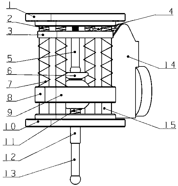
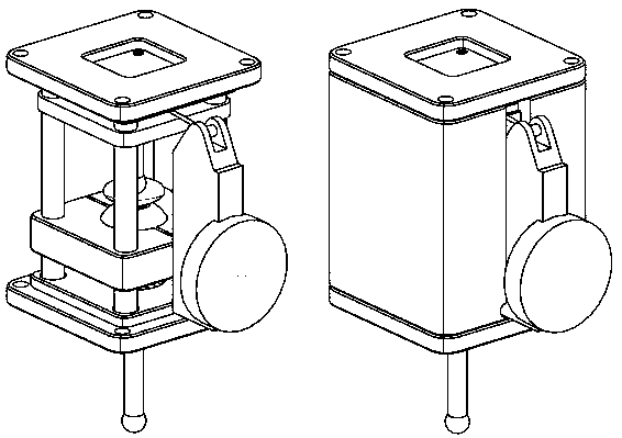
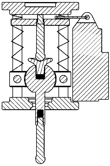
[0023] see Figure 1-6 , a 3D edge finder based on a ball joint, the edge finder includes an upper top cover 1, an upper and lower floating plate 3, an internal adjustment probe 5, a concave spherical part 6, a swing return spring 11, and a dial indicator 14 and the main body bottom plate 10, the upper top cover 1 is connected with the upper and lower floating plates 3, and the upper top cover 1 and the upper and lower floating plates 3 are also provided with a downward pressure return spring 2 and an internal adjustable gauge 4, and the internal adjustable gauge One end of the head 4 is connected to the upper and lower floating plates 3, and the other end is connected to the dial indicator 14; the internal adjustment measuring head 5 is located below the upper and lower floating plates 3, one end is connected to the lower end of the upper and lower flo...


PUM


Abstract

The invention discloses a 3D mechanical edge finder based on a bulb universal joint. The edge finder comprises an upper top cover, a vertical floating plate, an inner adjusting measuring head, a concave spherical surface part, a reset spring, a bulb lock block, a measuring head, a dial indicator and a main bottom plate. The upper top cover and the vertical floating plate are connected, and a pressing reset spring and an inner adjustable header are arranged between the upper top cover and the vertical floating plate. The inner adjusting measuring head is located below the vertical floating plate, and a push-up reset spring is arranged on the side face of the inner adjusting measuring head. A bulb convex lock block and a bulb concave lock block are arranged on the outer side of the concave spherical surface part. The lower end of the concave spherical surface part is connected with the swing reset spring, a guide rod is arranged on the side face of the swing reset spring, and a bulb rodand a measuring head are arranged below the main bottom plate. According to the 3D mechanical edge finder based, the limitation that a traditional edge finder can only be used on a transverse machineis broken through, and the edge finder can approach a workpiece in any direction; the tool setting precision is high, the error rate is low, the structure is simple, and manufacturing cost is low; andthe 3D mechanical edge finder can be widely popularized on the market.

Description

technical field [0001] The invention belongs to the field of mechanical processing, and in particular relates to a 3D edge finder based on a ball joint. Background technique [0002] CNC machining refers to a process method for processing parts on CNC machine tools. It is a mechanical processing method that uses digital information to control the displacement of parts and tools. Problems and realize high-efficiency and automatic processing, and the most important thing in CNC processing technology is to control the accuracy of tool setting. At present, the tool setting process in most factories is operated by workers with bare hands, and free-hand tool setting will have a great impact on the accuracy of the workpiece, and it is easy to cause errors in the processing and manufacturing of the workpiece. Therefore, an edge finder that is simple, practical, cheap and can improve the accuracy of tool setting needs to be developed urgently. Contents of the invention [0003] T...

Claims


Application Information

Patent Timeline
Patent Type & Authority Applications(China)
IPC IPC(8): B23Q17/22
CPCB23Q17/22
Inventor 梅贤慧许士杰陈心怡唐晨刘非凡
Owner NANJING INST OF TECH
Learn More