An automatic and precise stretching and positioning device and method for ultra-fine metal bridge wires

A positioning device and bridge wire technology, applied in auxiliary devices, metal processing equipment, auxiliary welding equipment, etc., can solve the problems of low accuracy, weak welding, poor consistency, etc., to improve relative position accuracy and ensure internal stress. Consistency, the effect of improving positional consistency

Active Publication Date: 2020-07-14
CHUANNAN MACHINERY PLANT CHINA ASTRONAUTIC SCI &TECH GROUP CORP
View PDF7 Cites 0 Cited by
  • Summary
  • Abstract
  • Description
  • Claims
  • Application Information

AI Technical Summary

Problems solved by technology

However, due to the extremely small size of the bridge wires and solder joints, the welding operation is completely manual. It is difficult to ensure the positioning of the two and the internal stress of the bridge wires. Often, the welding is not firm and the stress of the bridge wires is uneven due to the position deviation of the bridge wires. The resulting difference in bridge resistance
Rework often occurs due to unqualified bridge wire welding, which has a negative impact on the on-time delivery and assembly quality of aerospace pyrotechnic devices
[0004] It can be seen from the above that there are deficiencies such as low precision and poor consistency in the bridge wire drawing process of bridge wire pyrotechnic products.
[0005] Judging from the existing domestic and foreign literature, there is no report on the method of solving the problem of precise tensioning of ultra-fine metal bridge wires for bridge wire pyrotechnics

Method used


Image

  • An automatic and precise stretching and positioning device and method for ultra-fine metal bridge wires
  • An automatic and precise stretching and positioning device and method for ultra-fine metal bridge wires
  • An automatic and precise stretching and positioning device and method for ultra-fine metal bridge wires

Examples


Embodiment Construction

[0034] Exemplary embodiments of the present disclosure will be described in more detail below with reference to the accompanying drawings. Although exemplary embodiments of the present disclosure are shown in the drawings, it should be understood that the present disclosure may be embodied in various forms and should not be limited by the embodiments set forth herein. Rather, these embodiments are provided for more thorough understanding of the present disclosure and to fully convey the scope of the present disclosure to those skilled in the art. It should be noted that, in the case of no conflict, the embodiments of the present invention and the features in the embodiments can be combined with each other. The present invention will be described in detail below with reference to the accompanying drawings and examples.

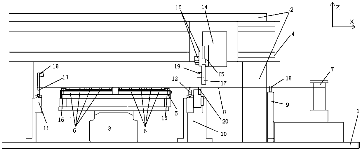
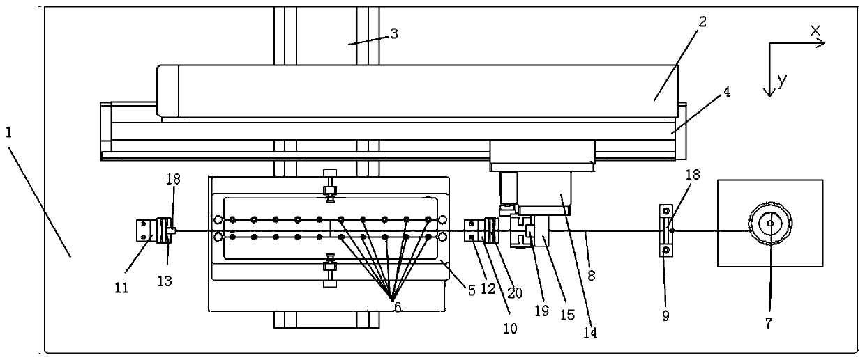
[0035] like figure 1 and figure 2As shown, this embodiment provides an automatic and precise positioning device for ultra-fine metal bridge wires. Compone...


PUM


Abstract

The invention discloses an automatic precise pull and coverage locating device and method for an extremely-thin metal bridge wire and belongs to the field of pre-welding preparation of bridge wire type initiating explosive device bridge wires. According to the method, initial positions of to-be-welded elements and the bridge wire are precisely located; the bridge wire is clamped through a wire drawing mechanism under the guidance of laser, so that oriented movement is achieved; finally, precise locating, over the to-be-welded elements, of the bridge wire is achieved, and pole needle welding points, needing to be welded, on the surfaces of the multiple to-be-welded element which are mounted on a clamping plate are covered with the bridge wire; meanwhile, the bridge wire is fixed to preset welding piles of the clamping plate for the to-be-welded elements through welding flux or adhesive, so that positional fixation, above the multiple mounted to-be-welded elements, of the bridge wire isachieved; positional precision of the pole needle welding points on the multiple to-be-welded elements and the bridge wire meets the bridge wire welding requirement; the problem that after primary bridge wire welding formation of multiple to-be-welded elements is completed, internal stress of a bridge wire is nonuniform is solved; and product welding conformance is improved.

Description

technical field [0001] The invention belongs to the technical field of pre-welding preparations for bridge wire type pyrotechnic products, and in particular relates to an automatic and precise stretching and positioning device and method for ultra-fine metal bridge wires. Background technique [0002] Bridge wire pyrotechnics is a typical aerospace pyrotechnic device, which is often used in the first stage of ignition. It uses a very thin (generally φ0.02mm) metal bridge wire with a certain resistance as a heating element. When working, pass a certain current to the bridge wire pyrotechnic product, and the current passes through the bridge wire through the metal leg of the pyrotechnic product. The bridge wire heats up rapidly under the action of the current, and ignites the energetic agent near the bridge wire after reaching a certain temperature. , and ignite the advanced charge step by step to produce gas or detonation energy output. This type has the advantages of mature...

Claims


Application Information

Patent Timeline
Patent Type & Authority Patents(China)
IPC IPC(8): B23K37/00B23K37/047
CPCB23K37/00B23K37/047
Inventor 杨梦龙谢章龙夏先友张小英詹亮邱伟
Owner CHUANNAN MACHINERY PLANT CHINA ASTRONAUTIC SCI &TECH GROUP CORP
Why Eureka
Try Eureka