Full-automatic punching machine mold

A fully automatic, stamping die technology, used in forming tools, manufacturing tools, metal processing equipment, etc., can solve the problems of adjusting the height of the punch die body, no springs, no settings, etc., so as to avoid the decline of processing quality and reduce dangerous accidents. , the effect of improving the service life

Inactive Publication Date: 2018-12-07
JIAXING WEITELA ELECTRICAL SCI & TECH CO LTD
View PDF8 Cites 5 Cited by
  • Summary
  • Abstract
  • Description
  • Claims
  • Application Information

AI Technical Summary

Problems solved by technology

[0004] The purpose of the present invention is to provide a fully automatic punching die to solve the above-mentioned background technology that there is no electro-hydraulic push rod, which makes it difficult for the user to adjust the height of the punching die body. The impact force of the lower template card and the back, without the first sleeve and movable rod, can not facilitate the user to limit the lower template

Method used


Image

  • Full-automatic punching machine mold
  • Full-automatic punching machine mold
  • Full-automatic punching machine mold

Examples


Embodiment

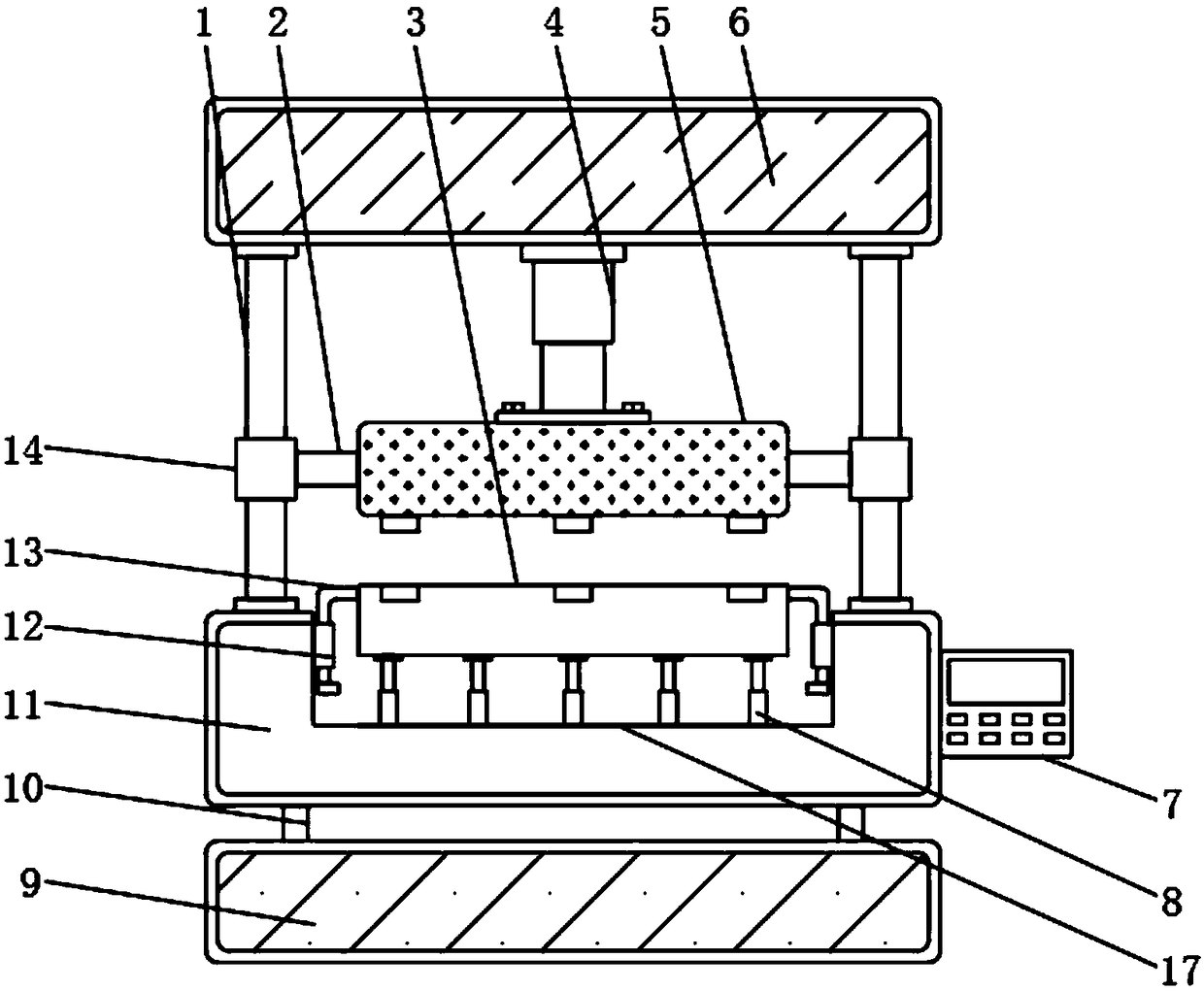
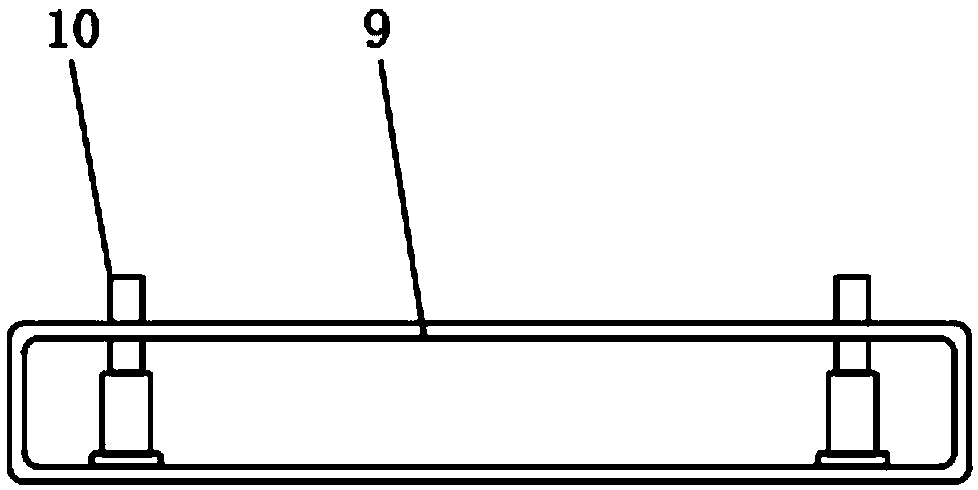
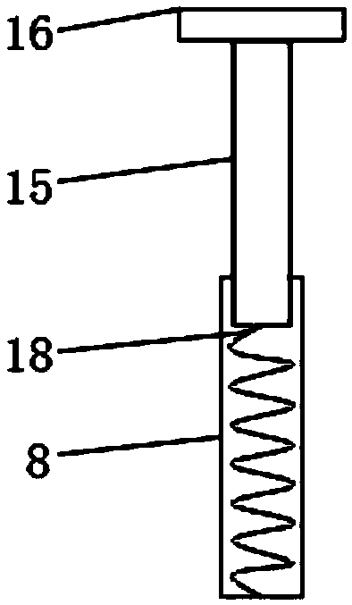
[0020] see Figure 1~3 , the present invention provides a technical solution:

[0021] A fully automatic punching die, comprising a punching die body 11, a hydraulic cylinder 4 and a lower template 3, a control switch 7 is fixedly installed on one side of the punching die body 11, and a slide bar 1 is fixedly installed on the top of the punching die body 11, and the punching The inside of the die body 11 is provided with a groove 17, and the bottom end of the stamping die body 11 is fixedly equipped with an electro-hydraulic push rod 10, the outside of the slide bar 1 is sleeved with a second sleeve 14, and the top end of the slide bar 1 is fixedly installed There is a first support platform 6, a bracket 2 is fixedly installed on one end of the second sleeve 14, and the hydraulic cylinder 4 is fixedly installed on the bottom end of the first support platform 6 near the side of the slide bar 1, and the bottom end of the hydraulic cylinder 4 The upper template 5 is fixedly inst...


PUM


Abstract

The invention discloses a full-automatic punching machine mold. The full-automatic punching machine mold comprises a punching mold body, a hydraulic cylinder and a lower mold plate; the punching moldbody is internally provided with a groove, the bottom end of the punching mold body is fixedly provided with an electric hydraulic push rod, a telescopic rod is embedded on the top end of a supportingrod, a spring is arranged in the supporting rod, an anti-sliding pad is fixedly arranged on the top end of the telescopic rod, the lower mold plate is arranged on the top end of the anti-sliding pad,and one end of the lower mold plate is fixedly provided with a movable rod. Through the electric hydraulic push rod, a user can adjust the height of the punching mold body conveniently, a worker canconveniently carry out operation, the spring and a telescopic rod are arranged, impact force of an upper mold plate and the lower mold plate after clamping can be relieved, the service life of the upper mold plate and the lower mold plate is prolonged, a first sleeve and the movable rod are arranged, the user can conveniently limit the lower mold plate, and the problem that due to position deviation of the lower mold plate, the machining quality is reduced is solved.

Description

technical field [0001] The invention relates to the technical field of punch dies, in particular to a fully automatic punch die. Background technique [0002] The punch mold is the "accessory" corresponding to the punch. The workpiece is plastically deformed under the combined action of the stamping of the punch and the resistance of the mold to complete the processing process. The punch mold is an indispensable part of the stamping process. The accuracy of the punch mold largely determines The machining accuracy of the workpiece is improved. [0003] However, the punch dies currently on the market are not equipped with electro-hydraulic push rods, which cannot facilitate the user to adjust the height of the punch die body. There are no springs and telescopic rods, which cannot relieve the impact of the upper and lower dies. A sleeve and a movable rod cannot be convenient for the user to limit the lower formwork. Contents of the invention [0004] The purpose of the pres...

Claims


Application Information

Patent Timeline
Patent Type & Authority Applications(China)
IPC IPC(8): B21D37/04
CPCB21D37/04
Inventor 朱桂林
Owner JIAXING WEITELA ELECTRICAL SCI & TECH CO LTD
Why Eureka
Try Eureka