
Modulo 2n subtracter design method based on quantum superposition state

A design method, a technology of quantum superposition, applied in CAD circuit design, instrumentation, calculation, etc.

Active Publication Date: 2018-12-04
EAST CHINA JIAOTONG UNIVERSITY
View PDF6 Cites 4 Cited by
  • Summary
  • Abstract
  • Description
  • Claims
  • Application Information

AI Technical Summary

Problems solved by technology

[0021] The purpose of the present invention is, in order to solve the quantum subtraction operation problem of quantum superposition state, propose a kind of modulus 2 based on quantum superposition state n Subtractor design method

Method used


Image

  • Modulo 2n subtracter design method based on quantum superposition state
  • Modulo 2n subtracter design method based on quantum superposition state
  • Modulo 2n subtracter design method based on quantum superposition state

Examples


specific Embodiment approach

[0085] In this embodiment, a mode 2 based on the quantum superposition state n Subtractor design method, said method utilizes basic quantum controlled gates to realize the design method of quantum half subtractor and resetter, quantum full subtractor and resetter, and consists of quantum half subtractor, quantum full subtractor and resetter bit quantum modulus 2 n The design method of the subtractor; finally use the designed modulus 2 n Subtractor implements modulo 2 based on quantum superposition state n Subtraction operation.

[0086] 1. The design method of quantum half reducer and reset device in this embodiment

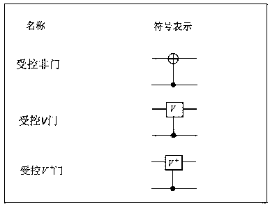
[0087] In this embodiment, four controlled gates are used to realize figure 2 The design circuit of the quantum half reducer is shown, and its schematic diagram is as follows image 3 Shown, represented by the symbol Q. The four controlled gates include a controlled NOT gate, two controlled V gates and a controlled V gate + Door.

[0088] apply the quant...


PUM


Abstract

Provided is a modulo 2n subtracter design method based on a quantum superposition state. The method uses a basic quantum controlled gate to realize design of a quantum half-subtracter and a repositor,a quantum full subtractor and a repositor, and design of an n-bit quantum modulo 2n subtracter formed by the quantum half-subtracter, the quantum full subtractor, and the repositors. Finally, the designed modulo 2n subtracter is used to realize modulo 2n subtraction based on a quantum superposition state. The method solves a problem of quantum modulo 2n subtraction in the quantum superposition state, and the quantum modulo 2n subtracter based on the quantum superposition state is designed. The method shows high efficiency of quantum information processing in signal processing. 2m n-bit integer modulo 2n subtraction can be realized by just 14n-13 basic operations. Using a classical computer to realize corresponding additive operation needs O(n2m) basic operations. An abstract figure is a quantum diagram of an n-quantum-bit quantum modulo 2n subtracter.

Description

technical field [0001] The present invention relates to a modulus 2 based on quantum superposition state n A subtractor design method belongs to the technical field of quantum circuit design. Background technique [0002] mod 2 n Subtraction is expressed as [0003] MS(b-a)=sign(b-a)×[(b-a)mod 2 n ] (1) [0004] Where a, b are n-bit positive integers. When b<a, sign(b-a)=-1, and when b≥a, sign(b-a)=1. (b-a) mod 2 n Yes (b-a) to 2 n Carry out the modulus operation, the operation rules are as follows [0005] [0006] In quantum computing, the information unit is represented by a qubit, which has two basic quantum states |0> and |1>, and the basic quantum state is called the ground state for short. A qubit can be a linear combination of two ground states, often called a superposition state, which can be expressed as |ψ>=a|0>+b|1>, where a and b are two complex numbers. [0007] Tensor product is a method of combining small vector spaces to form a...

Claims


Application Information

Patent Timeline
Patent Type & Authority Applications(China)
IPC IPC(8): G06F17/50
CPCG06F30/36
Inventor 范萍黎海生丁振凡殷爱菡
Owner EAST CHINA JIAOTONG UNIVERSITY
Learn More