Folding frame, display and electrical appliance

A technology of folding frame and rotating connection, which is applied in the direction of instruments, supporting machines, machine tables/supports, etc., and can solve problems such as visual fatigue of users, damage to the surface of flexible structures, and creases of supported flexible structures.

Pending Publication Date: 2018-11-30
王希哲
View PDF0 Cites 6 Cited by
  • Summary
  • Abstract
  • Description
  • Claims
  • Application Information

AI Technical Summary

Problems solved by technology

[0007] One of the technical problems to be solved by the present invention is to provide a folding frame that overcomes the defects that the existing folding frame structure causes creases on the supported flexible structure and damages the surface of the flexible structure
[0008] The second technical problem to be solved by the present invention is to provide a display that overcomes the defects of existing displays that cannot be folded, large in size, and inconvenient to carry
[0009] The third technical problem to be solved by the present invention is to provide an electrical appliance, which overcomes the defects that the display of the existing electrical appliance cannot be folded, which causes the appliance to be large in size and inconvenient to carry, or the small size of the display of the appliance easily causes visual fatigue to the user

Method used


Image

  • Folding frame, display and electrical appliance
  • Folding frame, display and electrical appliance
  • Folding frame, display and electrical appliance

Examples


Embodiment Construction

[0078] The present invention will be further described below in conjunction with the accompanying drawings and embodiments.

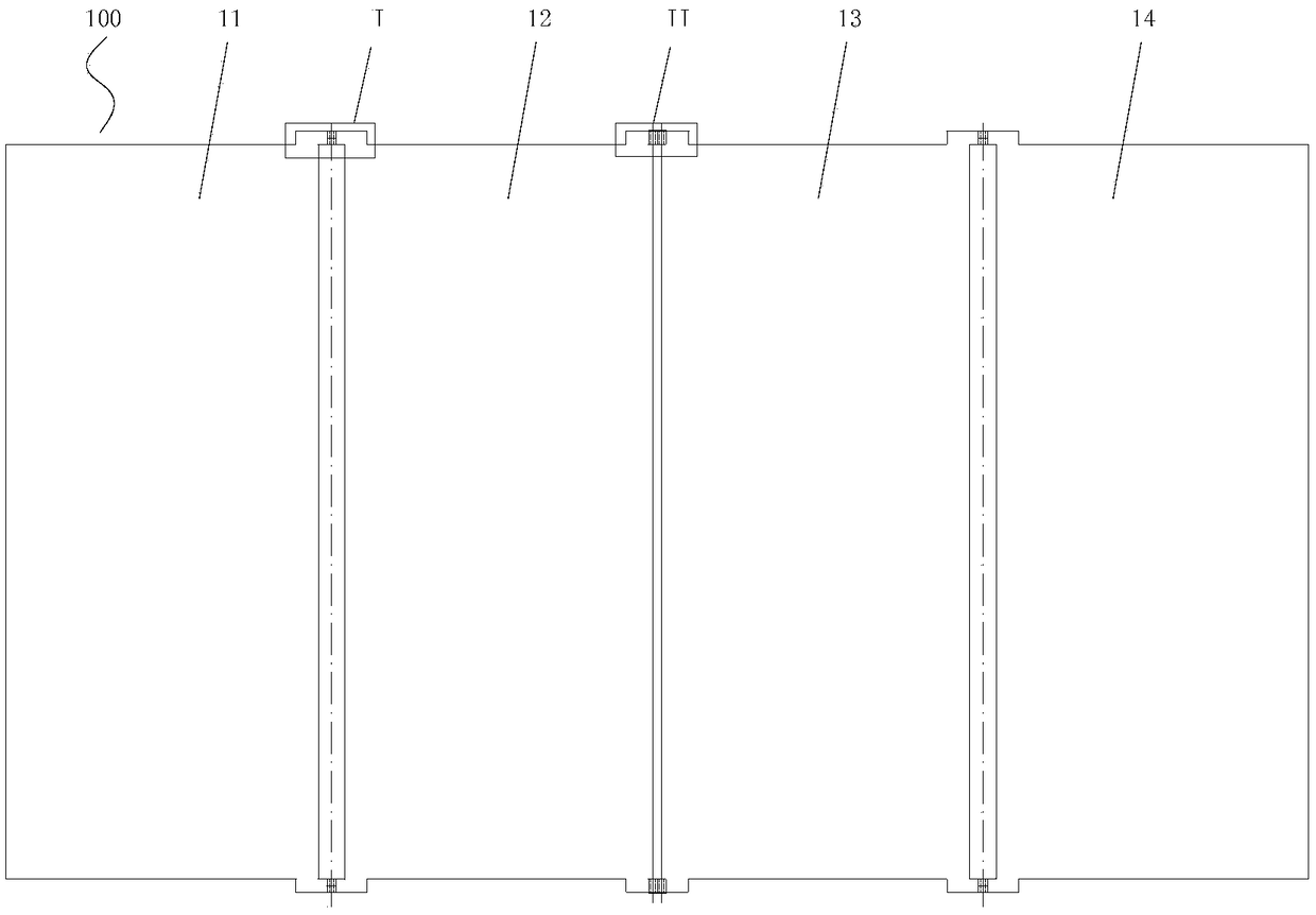
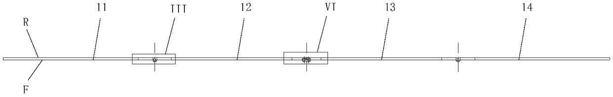
[0079] Such as figure 1 , figure 2 As shown, the folding frame 100 of the present invention includes hinges 11 , 12 , 13 , 14 , a rotating connection structure and a limiting structure.

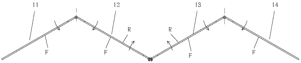
[0080] Adjacent hinges 11 and 12, 12 and 13, 13 and 14 are connected through a rotating connection structure, so that the folding frame can be moved from figure 1 , figure 2 The unfolded final state shown to Figure 16 The fold shown in its final state.

[0081] Such as figure 2 As shown, the folding frame 100 and its hinges 11, 12, 13, 14 include a front side F on one side of the folding frame and a rear side R on the other side of the folding frame.

[0082] The position-limiting structure ensures that the front sides F of the folding leaves 11, 12, 13, 14 of the folding frame 100 are located in the same plane in the final unfolded state.

[0083] The rotat...


PUM


Abstract

The invention discloses a folding frame, a display and an electrical appliance. The folding frame comprises folds and a limiting structure; the folds are connected through rotating connecting structures and can be unfolded or folded; the folding frame and the folds each comprise a front side face and a rear side face; the limiting structure guarantees that under the unfolding state of the foldingframe, the front side faces of the folds are located on the same plane; the rotating connecting structures comprise the first rotating connecting structure and / or the second rotating connecting structure; the folds connected by the first rotating connecting structure rotate towards the sides, close to one another, of the front side faces, and the folds connected by the second rotating connecting structure rotate towards the sides, close to one another, of the rear side faces; and under the folding state, circles constituted through the minimum bending radii of flexible films can be contained between the side faces of the folds connected by the first rotating connecting structure and the rotating axis, the side faces of the folds connected by the second rotating connecting structure are matched with the flexible films, or gaps are formed between the side faces of the folds connected by the second rotating connecting structure and the flexible films. The display comprises the folding frame and a flexible display attached to the folding frame. The electrical appliance comprises a circuit module, a power module and the display, the power module is electrically connected with the circuit module and the display, and the display is electrically connected with the circuit module. The display and the electrical appliance can be folded, and collecting and carrying are convenient.

Description

technical field [0001] The invention relates to a foldable support for supporting a flexible structure, and also relates to a display using the foldable support and an electrical appliance using the display. Background technique [0002] Utilizing the folding structure characteristics of the folding frame, the unfolded final state of the frame body can be transformed into the folded final state, so as to achieve the purpose of reducing size and facilitating storage and storage. [0003] Although the existing folding frame structure can realize the folding and retracting of the frame body itself, it is not suitable for the folding of supporting flexible structures (such as flexible films, etc.), because the hinged structure of the existing folding frame makes the folding frame fold , it is easy to cause creases in the flexible structure supported by the folding frame, causing damage to the surface of the flexible structure. [0004] Existing electrical displays, such as liqu...

Claims


Application Information

Patent Timeline
Patent Type & Authority Applications(China)
IPC IPC(8): G09F9/30F16M11/00F16C11/04
CPCF16C11/04F16M11/00G09F9/301G06F1/1641G06F1/1647G06F1/1652G06F1/1681G06F2200/1633G06F1/162
Inventor 王希哲
Owner 王希哲
Why Eureka
Try Eureka