
An anti-sway device for lifting of a large-scale liquid tank and a matching method thereof

A liquid tank hoisting and anti-sway technology, applied in the directions of transportation and packaging, load hoisting components, etc., can solve the problems of large damage to the hull of the tank, large surface area of ​​large liquid tanks, and shaking.

Pending Publication Date: 2018-11-30
大连船舶重工集团海洋工程有限公司
View PDF0 Cites 2 Cited by
  • Summary
  • Abstract
  • Description
  • Claims
  • Application Information

AI Technical Summary

Problems solved by technology

The liquid tank is hoisted and installed by a sea crane. During the hoisting process, due to the large surface area of ​​the large liquid tank, it is greatly affected by the wind disturbance; Shaking, it is easy to collide with the side wall of the hull, and the force generated when the liquid tank shakes is extremely destructive to the tank and the hull

Method used


Image

  • An anti-sway device for lifting of a large-scale liquid tank and a matching method thereof
  • An anti-sway device for lifting of a large-scale liquid tank and a matching method thereof
  • An anti-sway device for lifting of a large-scale liquid tank and a matching method thereof

Examples


Embodiment 1

[0053] Embodiment 1: The situation where a large liquid tank is lowered into a cargo hold located in a small dock

[0054] Such as Figure 6 As shown, the system parameters are: the maximum wind force of the sixth-level wind is 7.14 tons. Four lifting lugs 11 are arranged on the wide body surface of both sides of the liquid tank to be placed in the cargo hold, and the lifting lugs 11 are respectively connected with four sets of steel wire ropes 1 in the present invention. Four cubic meters of floating tank 3 volumes, four tons of dead weight, one meter high, two meters long and wide, and the center of gravity is at the bottom. Water tank 48*3*3 meters, adjustable rope length 7 meters>(28.23-22.42) (actual rope release amount), fixed pulley block 6 must bear the pulling force and be 8 tons.

[0055] Wire rope 1 and fixed pulley block 6 are connected to the wire rope at the lugs on both sides of the tank body, and wire rope 1 bypasses the first pulley 2 and the second pulley 5...

Embodiment 2

[0057] Embodiment 2: The situation in which a large liquid tank is lowered into a cargo hold located in a large dock

[0058] Such as Figure 7 As shown, there are two cargo holds of liquid tanks to be installed symmetrically in the large dock. The maximum wind force of the sixth-level wind is 7.14 tons. Four lifting lugs 11 are arranged on the wide body surface of both sides of the liquid tank to be placed in the cargo hold, and the lifting lugs 11 are respectively connected with four sets of steel wire ropes 1 in the present invention. Four cubic meters of floating tank 3 volumes, four tons of dead weight, one meter high, two meters long and wide, and the center of gravity is at the bottom. Water tank 48*3*3 meters, adjustable rope length 7 meters>(28.23-22.42) (actual rope release amount), fixed pulley block 6 must bear the pulling force and be 8 tons.

[0059] Wire rope 1 and fixed pulley block 6 are connected to the wire rope at the lugs on both sides of the tank body,...


PUM


Abstract

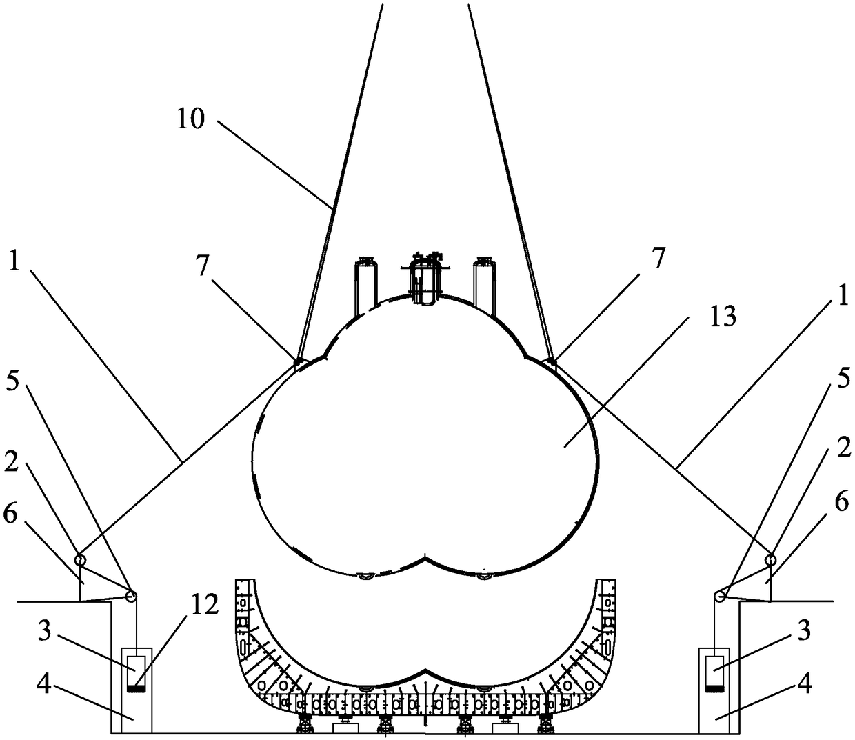
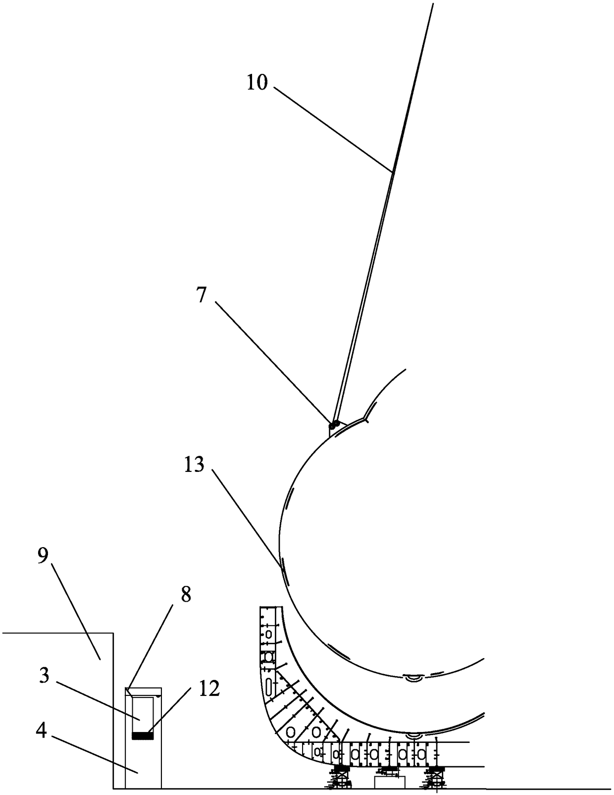
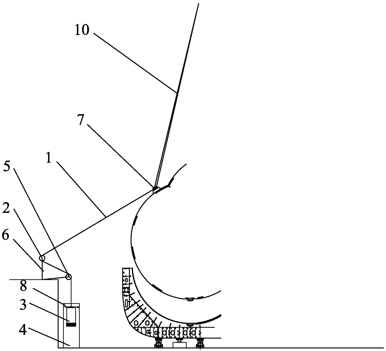
An anti-sway device for lifting of a large-scale liquid tank is disclosed. The device includes liquid tank lifting points (7) symmetrically arranged on the upper surfaces of the pear-shaped middle wide parts at two sides of a flat pear-shaped liquid tank (13) and used for hooking lifting ropes (10) of lifting equipment; guiding pulley blocks (6) symmetrically arranged on two sides of the liquid tank (13) and fixed to dock outer ends or supporting docking blocks; and balance weight assemblies connected to the liquid tank lifting points (7) through the guiding pulley blocks (6) with steel wire ropes (1). When then liquid tank is influenced by external force and sways, the steel wire ropes pull floating boxes out of water boxes, and at this time, the gravity of the floating boxes is greater than floating force, and the difference between the gravity and the floating force acts on the liquid tank lifting points through shackles to form restoring force the direction of which is opposite tothe liquid tank swaying direction. The damping generated by the overall anti-sway system counteracts swaying energy of the liquid tank, thus achieving an anti-sway objective.

Description

technical field [0001] The invention relates to the field of hoisting large liquid tanks for ships, and more specifically relates to a hoisting anti-sway device for large liquid tanks and an arrangement method thereof. Background technique [0002] The large liquid tank for acetylene and acetylene ships weighs 1,737 tons, is 40.966 meters long, 38.850 meters wide and 31.650 meters high. Its shape is quite special, the bottom and the shoulders on both sides are inwardly recessed to form a flat pear-shaped tank. This large acetylene and acetylene marine liquid tank needs to be hoisted into the cabin. When entering the cabin, the distance between the side wall of the cabin and the hull structure is very narrow, about 300mm. The liquid tank is hoisted and installed by a sea crane. During the hoisting process, due to the large surface area of ​​the large liquid tank, it is greatly affected by the wind disturbance; Shaking, it is easy to collide with the side wall of the hull, a...

Claims


Application Information

Patent Timeline
IPC IPC(8): B66C13/06B66C13/08B66C1/12
CPCB66C1/12B66C13/06B66C13/08
Inventor 霍力强郭相维黄禄明张永杰曲广杰李虎清屠振乾宋庆闯
Owner 大连船舶重工集团海洋工程有限公司
Learn More